A din rail refers to a special mounting strip placed in switch cabinets and similar prefabricated structures. Its main purpose is to serve as the basis for mounting RCDs, circuit breakers and other protective devices serving the power supply line. A standard-sized din-rail can accommodate several samples of devices of various classes, including powerful magnetic starters. It all depends on what is the specific width of the modular automaton, determined by its functional purpose.
Types of din reiki
Depending on the shape of the mounting plate, known samples of products of this class are divided into the following types:
- rails of type ТН (their types - ТН 15, ТН 35, ТН 75);
- Class C products (C20, 30, 40, 50);
- G-type trims (G 32).
The first of these designs resembles the letter of the Greek alphabet "omega" in shape and is the most common among industrial designs. Traditionally, the cases of electric meters and automatic machines are mounted on it.
In C-shaped models, the side edges are bent inward, so that its profile allows you to fix the terminal blocks of a special shape and design. The G-bar is a slightly modified modification, used extremely rarely and used for the same purpose. The length of these fasteners, depending on the manufacturer, varies from 7.5 cm to 2 meters, which allows you to place from 4 to 96 pieces of protective devices with a standard width of one machine module.
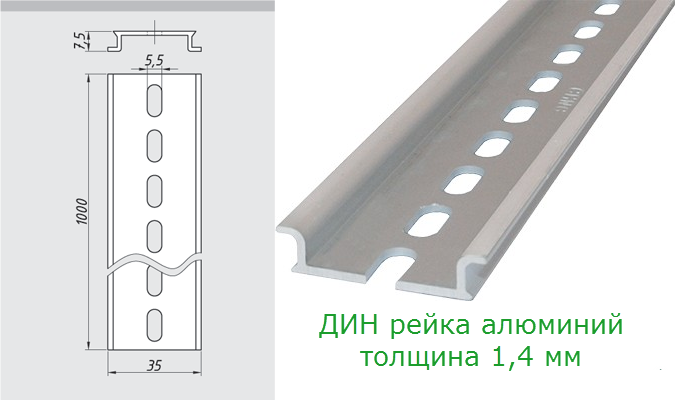
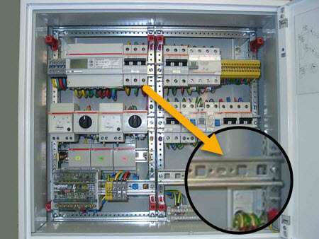
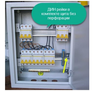
According to their design, din-rails can be perforated - with holes filled along the entire length - and solid or cast.
The advantage of the first designs is in the ease of installation, since if there are holes filled with 10-15 mm increments, it is much easier to fix the steel rail. But cast samples are more durable and reliable. They do not deform when there are a large number of machines in the switchboard.
Application features
 DIN rail is a foreign invention, which got its name from the German standard, designated as DIN 43880-1988. In our country, their use is regulated by GOST R IEC 60715-2003. These products are sometimes called mounting rails. The full name is: "mounting rail for fixing protective devices in low-voltage distribution and control equipment for electrical networks."
In accordance with this definition, its scope applies to the following cases:
- the need to install electrical meters and other samples of measuring equipment in the distribution cabinet;
- the need for the placement of protective equipment there (RCD, difavtomatov, voltage relay and the like);
- if desired, mount special connecting fittings in the cabinet.

The decisive factor determining the capacity of such a rail is the width of the module of the machine or similar protective equipment installed on its basis.
When evaluating the width of the machines proceed from a specific number of protective devices used in the shield, which can have a single-pole or multi-pole design. The second option concerns three-phase networks. In the general case, its application is limited by this particular set of functions, but in some situations other directions of using the din rail are possible.
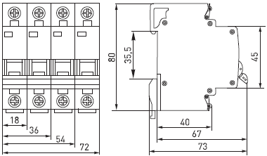
Dimensions and installation method
 In living conditions, standard trims with a profile width of 35 mm (TH 35), with a shelf height of about 7.5 mm, are traditionally used.Various product versions may differ in the declared profile thickness (1-1.5 mm) and the diameter of the holes filled during perforation (4 or 5 mm). For their fastening on the guides of the distribution panel, bolts of the corresponding standard size will be required.
The installation product is fixed at the two extreme points of the bar so that no parts protruding beyond the slice of the guides are formed. That is, along the length of the workpiece, they are selected exactly in size, for which the lateral excess is cut off in advance.
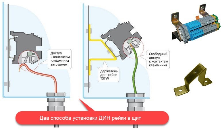
In hard-to-reach places with difficult working conditions with modular equipment, it is allowed to install holders for din rails of a special design. Such guides, if desired, allow you to rotate them at a convenient angle.
Module Width Calculation
The dimensions or dimensions of the circuit-breakers mounted on a din-rail are usually calculated taking into account the following considerations:
- what total number of these devices is planned to be installed in accordance with the used wiring diagram;
- what type of meter (meter) and circuit breakers are supposed to be mounted on it;
- what is the minimum clearance between these devices should be left.
If two machines or RCDs can be mounted practically close to each other, it is necessary to install the devices next to the electric meter at a certain distance (at least 1-2 centimeters).
When calculating the number of instruments that fit on a dyn-rail, their functional purpose must be taken into account. A bipolar circuit breaker is wider than a bipolar.
Materials for manufacture and load characteristics
The material from which a particular din-rail is made must correspond to its purpose. This means that it is necessary to take into account the expected loads, depending on which steel or aluminum products are selected. The first of these samples in their structure are more durable and can withstand extreme loads with a minimum thickness of only 1 mm.
Critical or ultimate loads are understood as situations when dimensional devices such as frequency converters, powerful magnetic starters or power three-phase machines are mounted on a rail.
Aluminum rails are able to "hold" the maximum stress of mechanical deformation only with a thickness of 1.5 mm. Accordingly, the set of power and protective equipment placed on them will be significantly limited.
Load characteristics
Since a typical DIN rail is produced as a profile product, it is able to withstand greater deformation loads than a metal plate of the same size. Typical load characteristics of din-rails are normalized by current standards for a number of signs, including the type of metal. Aluminum strips are available in the following versions:
- 1 mm thick rails designed for the installation of single modular devices: circuit breakers, RCD units, power modules;
- 1.1 mm strips intended for installation of single devices placed in several rows;
- the same products, but with an indicator of 1.4 mm, designed for modular equipment of any class and weight.
All these products are cut into pieces of the desired length before installation.
The kit may include steel rails with a thickness of 1.0 mm, the load capacity is similar to an aluminum rail with a thickness of 1.5 mm. They can withstand maximum loads without restrictions on weight and number of seats within the allowable size. In addition, manufacturers of switchboard equipment often equip distribution cabinets with rails of a non-standard profile.
How to choose racks for installation in a cabinet
 Since the width of the 1 DIN machine is a determining factor when choosing the right size of din-rails, you need to familiarize yourself with the assortment of metal products. The most common samples are represented by steel rails with standard sizes: thickness 1 mm and length up to a meter. They are distinguished by their versatility, and at a price noticeably cheaper than aluminum counterparts.
Immediately before use, they are cut into blanks of the right size for the dimensions of the housing of ready-made switchboards. In addition, each specific rail is adjusted in length to the required size. When assembling a new shield, its dimensions are selected based on the finished rails plus a small margin.
The size of the din rail machine is crucial in the design of switchgear of various classes. Only with this indicator in mind, it is possible to correctly calculate its operational parameters and the permissible load on the supporting structural elements.