The hydraulic accumulator in the water supply system can be called not only a liquid storage device, but also a protective element, since one of its functions is to smooth out water hammer. The pump instruction manual contains a technical parameter - the number of on and off cycles or the permissible frequency. Using the hydraulic tank, you can extend the life of the equipment and reduce repair costs.
The purpose of the accumulator in the water supply system
A hydraulic accumulator is a metal container for accumulating a supply of water. If the system did not have this important element, the pump would have to turn on each time when the tap opened in the house, the washing machine turned on, or people used a shower. Due to the supply of fluid, the pump is turned on less frequently and saves a resource.
GAs have different volumes. It depends on the pressure settings and the size of the storage tank. On average, a stolitrovy capacity in working condition can accommodate 30 - 35 liters of liquid. These data are needed to determine how much water needs to be stored in a family of 2, 3 or 4 people. The lower the pressure, the more water is placed inside. With an increase in indicators, the volume of liquid decreases.
Installing a hydraulic accumulator for water supply systems with your own hands does not present any special difficulties. A beginner can do this by first reading the manual or watching a video where the process is shown in practice.
Types of devices
Distinguish GA at the location. Large containers are usually placed in the attic of a private house or above the distribution unit, so that the force of gravity acts on the liquid, and it flows by gravity into the pipe. There are models of accumulators that can be installed anywhere in the system, even below the intake level. The process of fluid intake into the house is regulated by sensors and is independent of gravity. An ancient analogue of the tank is a water tower.
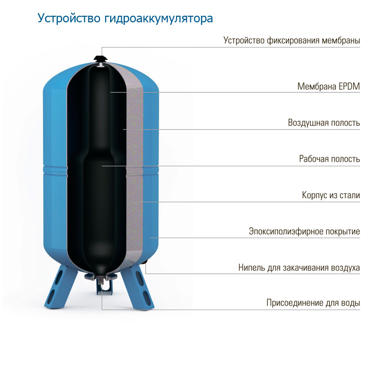
One of the varieties of GA does not provide for the presence inside the tank of anything but water and air. The amount of air mixture must be constantly monitored. This is not very convenient, so manufacturers produce membrane or balloon models.
Membrane GA
Inside the accumulator is a rubber membrane. On one side is liquid, on the other is an air mixture. The intake of water occurs up to a certain point, it depends on the pressure settings. As the water compartment fills, air is compressed. As soon as the pressure reaches a critical level, the sensor is triggered and the pump turns off. When opening the tap, fluid from the hydraulic tank is first consumed. When the pressure drops, the lower settings are triggered and the equipment starts up again.
Distinguish between red and blue tanks. The first are designed for closed heating systems and are designed for less pressure. Rubber inside is technical and is not intended for storage of drinking water. In blue HA, the membrane is made of food rubber.
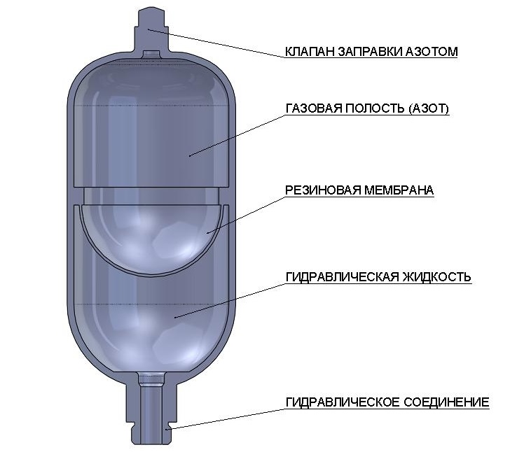
Balloon GA
Cylinder models have a rubber container inside, the neck of which is hermetically connected to the inlet pipe.The liquid entering inside does not come into contact with the walls of the container, but is completely in the rubber pear. The second half of the tank is filled with compressed air. Further, the principle of operation of the cylinder accumulator repeats the membrane method of adjusting the on and off of the pump. Tanks with a volume of over 100 liters have a special valve through which you can periodically bleed the air mixture.
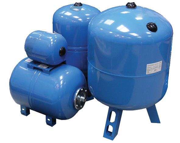
Horizontal and vertical models
Horizontal and vertical performance accumulators exist only for ease of use. If the container will be installed in a small bathroom, it is better to buy a vertical model, which will take place up to the ceiling. There are special mounts that allow you to mount it to the wall. Horizontal models are more stable, but require more space. They are usually placed in basements or technical rooms. They have legs and holes for fixing in the floor.
Place of capacity in the water supply system
In water supply systems, the accumulator is located after the pump, in front of the inlet pipe. At this point, he is able to control pressure and perform protective functions, for example, with a water hammer. Water hammer occurs when the valve is closed abruptly and at the same time the pump is running. The liquid by inertia moves to the exit, when it is blocked by movement, a backward wave occurs. It collides with an oncoming mass of liquid and pipe damage occurs. The absence of oncoming flow protects the line from rupture.
Some customers confuse the storage tank with an expansion tank. The second is designed to compensate for fluid loss during its heating and is installed in heating systems. When the liquid evaporates, an additional portion comes from the water supply.
When there is a power outage, there is a small supply of water that can be used for domestic purposes.
In addition to the protective and cumulative function, the GA serves to maintain a constant pressure of water in the system. It may slightly decrease when the tank runs out of fluid and the pump is about to turn on.
When a hydraulic tank is not needed
In irrigation systems, a hydraulic accumulator is not needed, since with a constant open tap the pump will work without shutting down. If a storage capacitance is present in this circuit, the equipment will often turn on, which will lead to premature exhaustion of the resource.
When buying a pump with an automatic system that assumes a smooth start of the engine, a GA is also not needed. Water hammer does not threaten the pipes, as the fluid flow moves slowly.
Connection methods and schemes
The connection diagram of the downhole pump to the accumulator will depend on the purpose of the equipment itself:
- When arranging a cold water supply system, the storage tank is installed in a certain place, and pressure sensors are connected using a nozzle to 5 inputs. So that the vibrations of the pump do not affect the accumulator, it is connected with a flexible hose. Such a system will need to be periodically inspected, before draining the water through a tap or a nearby pipe cut into the trunk.
- In a block of flats with a centralized water intake, the GA is mounted in front of the pump, that is, the tank is filled from the central pipe and transported to the consumers using the pump. In this case, the GA compensates for the low pressure of the central line.
- If the system has a boiler, the accumulator is connected to it.
These are the simplest schemes to quickly establish a water supply.
Connection to the submersible pump
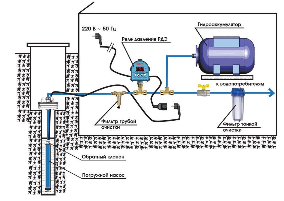
Not always the technical characteristics of the well allow you to install a powerful submersible pump in it. For example, if the casing is too narrow and the well is deep. In such a situation, it is necessary to select a deep unit, the power of which is enough to lift the liquid from depth to the storage tank.It can be located in a caisson or on the surface of the earth near the well.
Further, another pump is mounted near the accumulator - a self-priming one, which will transport water to the house. Another accumulator is installed in the room, which regulates the pressure in the system and controls the operation of the second pump.
The second tank should be membrane or balloon. So that the liquid does not stagnate in the first container, its volume should not be very large. A hydraulic accumulator can be connected directly to a submersible pump only if the parameters of the well and the power of the electrical equipment are fully consistent.
Connection to surface pump or pump station
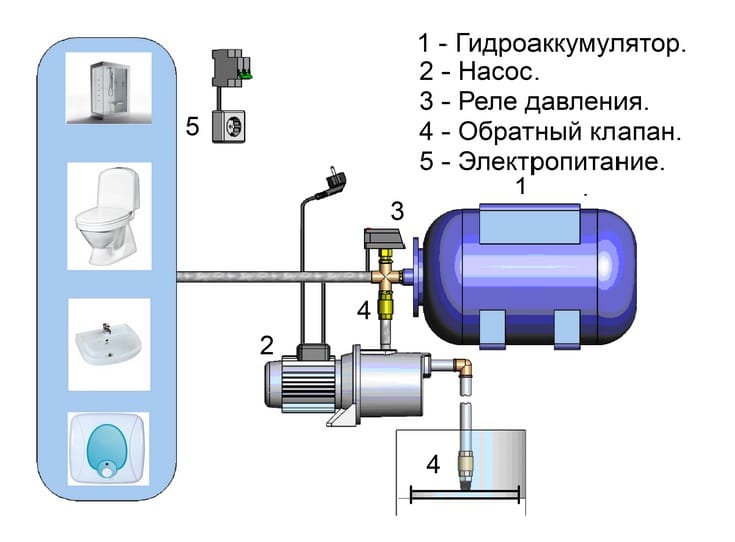
At the surface pumping stations, a hydraulic accumulator is included in the kit, therefore, it is recommended to install an additional tank if you need to protect the equipment from frequent switching on or have a large supply of water for any reason. The GA is mounted after the station.
To a surface centrifugal pump, to which a storage tank is not attached, it can be connected using a nozzle for 5 outputs:
- The fitting is connected to the tank using a flexible hose.
- Mounted pressure gauge and relay.
- The pressure gauge, relay contacts are connected to the pump and the network.
- The pump joins.
When sealing the joints, it is better to use tow, since the FUM tape quickly deteriorates. After checking the scheme of the pumping station with a hydraulic accumulator, you can test the system.
Scheme with two hydraulic tanks
If new household appliances that consume liquid have appeared in the house, it makes sense to add a few more hydraulic tanks to the system. There may be 2 or more. The more, the less often the pump turns on and the longer the engine wears out.
All accumulators are connected in parallel. The advantage is if one of them breaks down, all the others will fulfill their functions. The installation of additional relays and pressure gauges is not needed - they are on the first tank.
How to connect the second and subsequent hydraulic tanks:
- a tee is installed at the entrance of the first;
- a pump is connected to one output;
- to the second - the next capacity.
For convenience, you can use plastic pipes so that the containers can be placed side by side if there are more than two. You do not need to change the relay settings.
Connection to the water heating element of the system
When water is heated in the boiler, an increase in pressure occurs. In a closed system, this can lead to accidents and injuries. To reduce overpressure, a hydraulic accumulator is installed as an expansion tank.
Excessive hot liquid will be poured into the civil water and then consumed for domestic needs. Hydraulic accumulators are used, the membrane of which is intended for hot liquids.
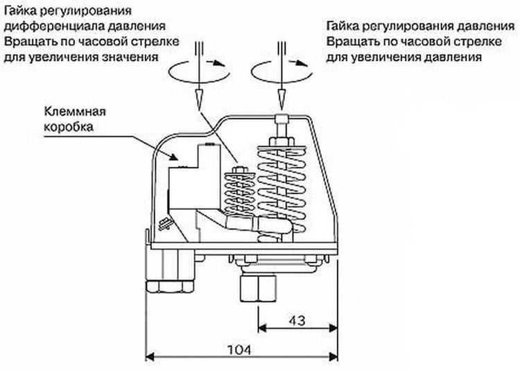
Pressure Switch Settings
Before starting the system, the pressure switch must be set correctly. The operation of the entire system will depend on this.
Connection Rules:
- for the water supply system should be allocated its own power line;
- cable to use a two-core copper;
- the wires must be earthed so that the current does not come into contact with water.
How to set up a pressure switch:
- Turn on the system.
- Focusing on the pressure gauge, use a wrench to set the lower pressure limit, tightening a large spring.
- Set upper limit with small spring.
- Check how the system works. If the pump does not turn on or off according to the settings, repeat the cycle again.
For convenience, the difference between the lower and upper threshold should not exceed 1 bar. In case of low pressure, the membrane will stretch very much, which can lead to rupture. A small difference between the two indicators will lead to frequent inclusion.
With large-capacity hydraulic accumulators, you can set the difference between the upper and lower pressure in 2 or 3 atmospheres.
To select the wires, it is better to invite an electrician so as not to spoil the equipment.
Accumulator Care
To extend the life of the GA, you must follow these rules:
- monitor for leaks - they can occur due to poor tightness or vibration transmitted from the pump;
- check the air pressure inside - its drop can cause rubber rupture and fluid leakage from the air valve;
- immediately respond to malfunctions in the system, as the problem may lie not only in the pump or hydraulic generator.
In order to find the problem in time, experts recommend checking the parts once every six months for wear. To do this, disconnect the hydraulic tank from the system, drain the liquid and remove the ring holding the membrane - in this place, rubber tears most often occur, after which air begins to flow into it. It is not difficult to replace a pear, it is important that it is selected similarly to the first one and that it meets the technical characteristics.