The graphic part of the internal water supply project includes an axonometric diagram of the water supply. It is used to visually examine the relative position of risers, pipelines, and plumbing points. Axonometry is created on the basis of water supply network plans.
Definition and purpose of the axonometric diagram of the water supply
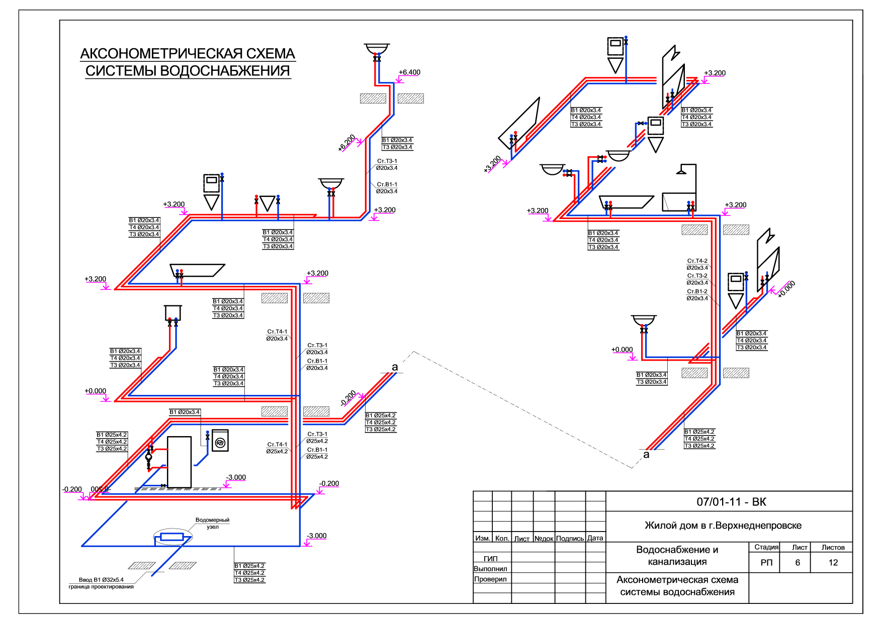 An axonometric diagram of a water supply system is a visual projection of a communications network in the x, y, z coordinate system. According to GOST standards, it is performed in frontal isometry with the left coordinate system. The image is executed at a scale of 1: 100 or 1: 200. It is drawn manually or using special computer programs. The projection of the water supply on all axes is postponed without resizing.
Axonometry of water supply simplifies the work of installers. They easily determine the location of devices, the diameter of the wiring pipes and risers. Also, the document is intended to perform the calculation.
Display of communications in the drawing
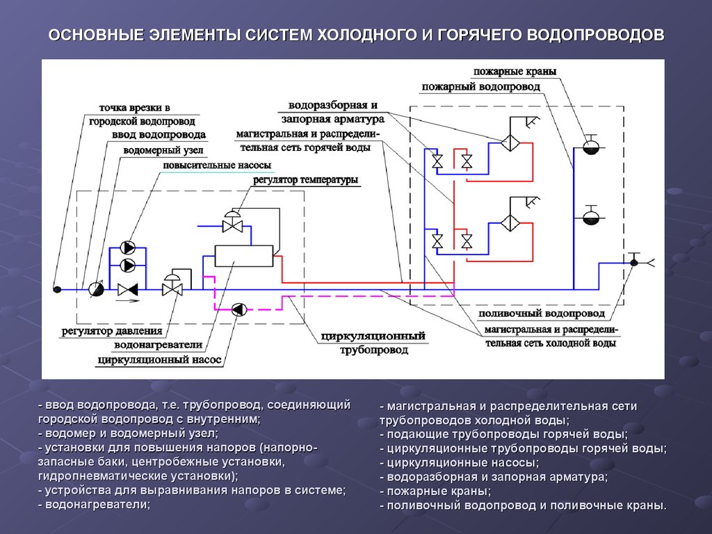
When working with the project of internal water supply and sanitation, general drawings are prepared on which the water supply and sewerage are combined. In axonometric diagrams, these networks are always separated. Horizontal sections of networks are transferred to the projection horizontally. On the plan, risers are located near the serviced group of devices, indicated by large points. On the diagram they are built vertically. The riser farthest from the input is fully displayed. The remaining elements are partially performed, indicating their brand. Vertical drawing of risers allows you to display the valves installed on them.
System parts displayed vertically on the project plan are drawn at an angle of 45 °. According to the trace, the cold water supply is laid 0.3 m above the floor, located with a slope of 0.002 towards the riser. This position is necessary for the flow of fluid. Connection to water fittings is made vertically.
All elements and nodes of the pipeline have their own marking and serial number on the drawing. Symbols indicate valves, faucets, plumbing fixtures, water meters. In the manufacture of axonometry, the norms for the height of the installation of water consumption points are used:
- sink and sink tap - 1.1 m;
- bath tap - 0.8 m;
- connection to the water heater - 0.8 m;
- eyeliner to the flushing tank - 0.65 m;
- fire crane - 1.35 m.
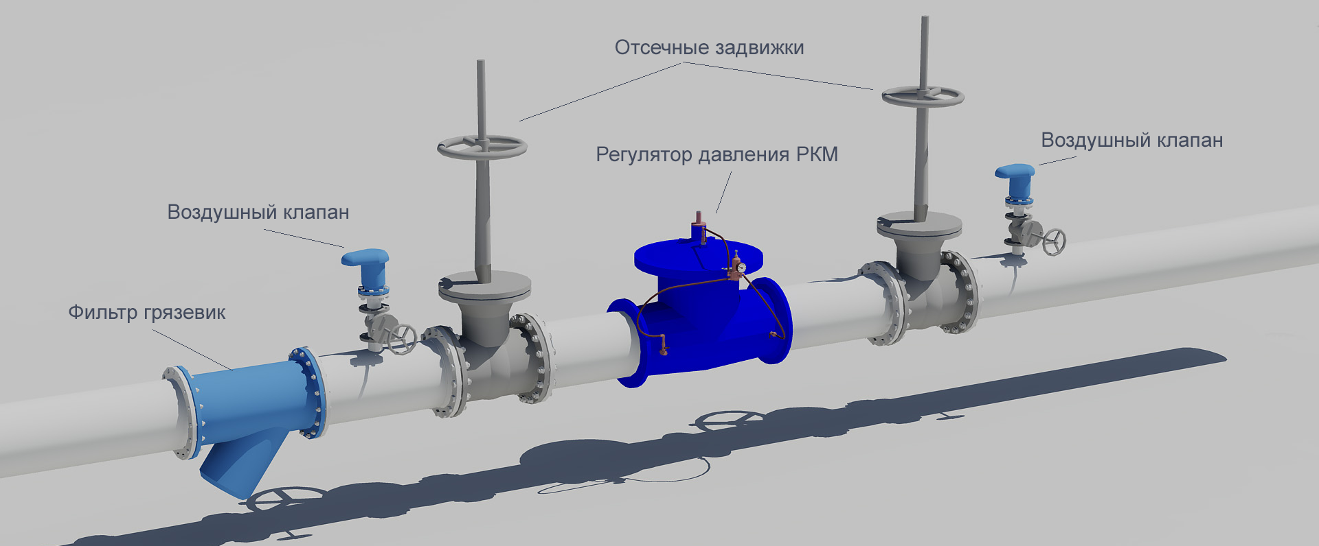
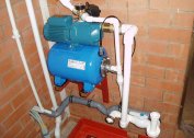
To block the flow of water in the event of an emergency and for preventive maintenance of the system, shutoff valves (taps, valves) are installed. They are located in key places:
- at the base of the risers (in a building from 3 floors);
- at the entrances to apartments, layering to tanks, water heaters, showers;
- in the place of connection to the street network;
- on watering valves;
- in the water meter assembly.
According to current standards, it is planned to install a water meter for each apartment in new residential buildings.
What data is indicated when drawing up the scheme
 The water network of the building indicates:
- image and marking of risers;
- the place of the pipeline to the building;
- floor branch wiring;
- shut-off and control valves;
- the height of the level of location of plumbing fixtures;
- sizes of pipeline sections (in mm);
- floor marks of all floors;
- water measuring unit in the basement;
- watering taps.
On the diagrams, using the leader, the diameter of the pipes, pipes, which are used when changing the wiring sizes, are indicated.It is necessary to note the places of water discharge, fire hydrants, instrumentation.
Sketch Design Features
Axonometry is developed for objects with a large number of pipeline elements and a passage diameter of 50 mm or more. There are fewer requirements for sketches than for drawings. The main attention on the projection is given to the drawing of devices. When the elements are superimposed on each other, image removal is performed. A network break and an offset are indicated by a dashed line. The procedure is necessary for a normal reading of all the details. If additional detail is required, individual nodes are drawn on a larger scale, for example 1:50.
At the entry point of the highway into the building, a relative and absolute elevation of the earth is affixed. It is located below the zero reference point - the floor of the first floor. A numerical indicator is written with a minus sign. If the installation of pressure tanks and pumps is provided, then their relative marks are indicated. In places of passage of polymer pipes through floor slabs, sleeves are installed. Such areas are marked on the diagram.
A complete axonometric diagram serves as the basis for the hydraulic calculation of the system. It determines sections of the highway with a constant flow of water. Nodal points are the sections of branch pipelines from risers. Tables (specifications) for materials and equipment are compiled for the scheme.