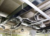
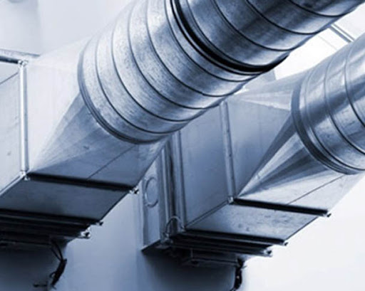
The fire damper for ventilation is a special device by which it is possible to eliminate the possibility of ingress of combustion products into the system. Thanks to them, residential and working premises are completely cut off from the source of ignition. They are made of heat-resistant and fire-retardant materials and maintain their performance under prolonged exposure to high temperatures. Installation and maintenance of these elements is organized and implemented in accordance with the standards applicable in construction practice.
Features of fire blockers for ventilation
For modern communication systems, on which the safety of people in case of fire depends, strict adherence to the requirements of current standards is mandatory. All of them are aimed at protecting working ventilation from gaseous and solid combustion products. In accordance with regulatory documents, the fire damper for ventilation systems blocks the channels of penetration into the rooms of combustion products and allows them to be removed from the danger zone.
The principle of operation and scope
The fire ventilation valve works according to the principle of most blocking elements, which are in the open state in the normal state. When a fire signal is received, they are transferred to the opposite state (“Closed”) using the drive mechanism. Different models of these devices differ in their design and the type of drive used.
Blocking valves for smoke and other combustion products are widely used in various facilities, including residential and public buildings. Within typical buildings, they are installed in the following places:
- walkways;
- corridor spans of buildings;
- elevator shafts and similar premises.
The devices are mounted in areas where pipelines intersect to remove smoke with ceilings between floors, as well as with walls and partitions of buildings.
Fire classification
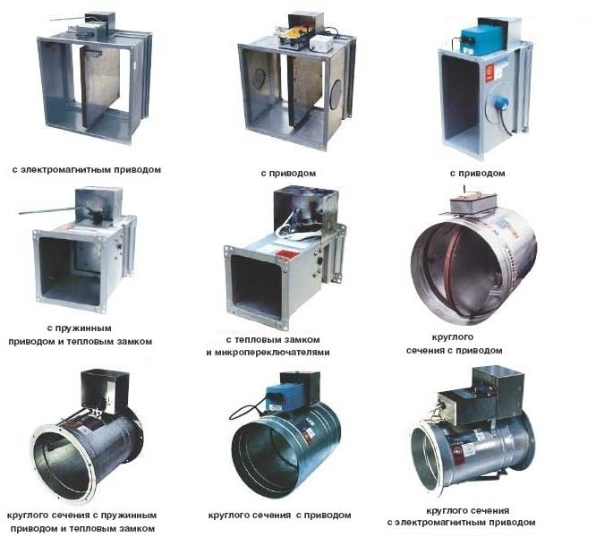
In accordance with the design features and the order of operation, fire valves for ventilation are divided into several types:
- normally closed or NC;
- normally open (BUT);
- double action;
- designed to remove smoky formations.
In the first samples, in the normal state, the blocking valve is closed, so that air does not enter the exhaust channel. In case of fire and an alarm, the valve opens, after which smoke is removed through natural or forced air flow through it. In BUT devices in normal mode, the valve is open and air moves freely through the ventilation system. After the fire alarm is triggered, the valve closes, eliminating the possible ingress of smoke into neighboring rooms. The most famous examples of such mechanisms include the KLOP-1 type fire damper.
Double-acting products combine the capabilities of the two options considered. They are triggered to close at the start of a fire, blocking the channel for smoke to enter a neighboring room, and automatically open when the fire ends. Smoke valves are special devices designed to remove combustion products and are elements of shut-off and control equipment. This type of device is installed in the places prescribed by applicable regulations.
By the method of placement within the ventilation system, the valves are divided into wall and channel. The former are mounted directly on the surfaces of structures without being connected to the existing system, while the latter are located directly in the ducts.
Damper types
To control the position of the dampers of the ventilation units, special mechanisms called servo-drives are used. In order for such a device to work, an electrical signal is supplied to it from the control module. There are several modifications of service drives, each of which is connected individually and needs a separate consideration.
Drive types
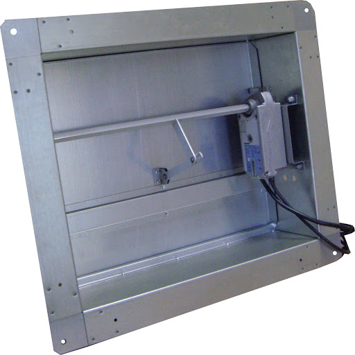
As a rule, fire dampers are equipped with two types of controls for their condition:
- The electromagnetic drive mechanism of the combined type, in normal mode, is in the closed state.
- An electric actuator, in the initial position, is de-energized and therefore the valve is kept closed.
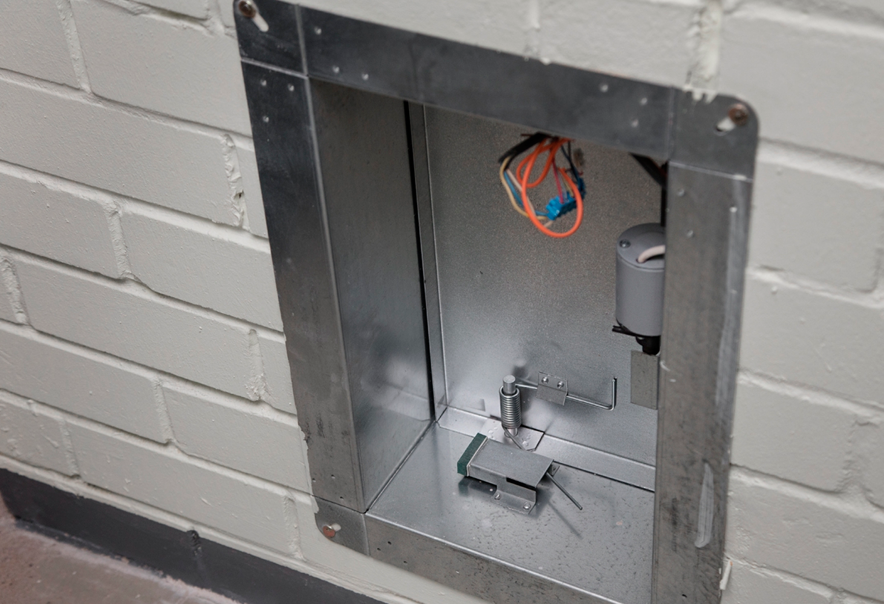
The fire damper for ventilation with an electric drive of a combined type operates as follows. When a fire is detected, a pulse is sent to the electromagnet from the sensitive sensors, under the influence of which the blocking voltage is removed from the valve. Its cover is displaced due to the elasticity of the spring in the mechanism. In the reverse state corresponding to the locked mode, the damper is returned manually.
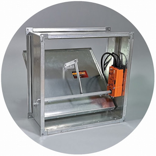
The electric actuator is also triggered by a pulse from the sensor, after which electric power is supplied to its terminals and the damper opens. It returns to its original (normally closed) position automatically upon command from the control panel or from the fire extinguishing system. On normally closed fire dampers, their manufacturers install reversible electric actuators of the BE, BLE, BEN and BEE designs. They are designed specifically for operation in critical conditions.
In some models of electric drives, the shutter moves from the initial state “Closed” to the working “Open” and vice versa by connecting power to the windings. The control signal for closing the valve here is the voltage supplied to the corresponding terminals of the device.
In older systems, fire dampers are fitted with a fusible insert and a typical spring return. Current regulations prohibit the use of such drives.
Features of the installation of the valve mechanism
For any type of system, the fire dampers for ventilation are positioned so as to block the return draft with any combination of fans and hoods available. When only one intake point is provided in the ventilation, 1 valve is installed within the duct to eliminate reverse thrust. With a more complex organization of the exhaust system (in the case of several work items), it is necessary to fulfill the following requirements:
- Each individual branch of the duct will need to install its own check valve, which eliminates the likelihood of reverse movement of air in the direction of the exhaust hood. Often they are supplemented by another sample mounted at the outlet of the ventilation system.
- A non-return valve is mounted in areas to which access is unrestricted.
For domestic use, both round and rectangular ducts of standard section are optimally suited. Ready-made solutions have been developed for them, providing for an arbitrary choice of a place for a check valve. The installation procedure in this case is no different from the connection of any typical ventilation element similar to it.
One of the practical solutions for exhaust systems equipped on the basis of plastic ducts or pipes is the placement of the valve mechanism in the channel connector. If necessary, the joint work of two types of systems (natural and forced), the following standard solutions are used:
- installing a tee next to the ventilation grill, followed by mounting the valve mechanism to the natural ventilation outlet;
- the use of lattices of a special design with taps for each of the systems.
For their fastening, experts recommend using liquid nails, or ordinary screws. The first of the options proposed above is preferable, since in this case it is more convenient to disassemble the system for the purpose of thorough cleaning, repair, or changing the circuit. To do this, simply remove the safety guard.
If you choose the option of mounting the valve on the inside of the grill, you will need to carefully seal the joints between it and the channel walls.