Warm floors can improve the energy efficiency of modern housing, make it more comfortable, and also significantly save money on heating. Of all the varieties of underfloor heating, water is the most difficult to regulate. But it is more popular due to cost-effective operation, durability and reliability. The mixing unit for underfloor heating is an important element of the control system. It maintains the necessary temperature inside the circuits and ensures the circulation of the coolant. The correct operation of the collector affects the functionality and efficiency of the water heating system.
Purpose of using the device
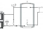
The use of a pump and mixing unit for the construction of a warm floor is necessary, since the water in the circuits must have a completely different, lower temperature than in conventional heating systems. Such a temperature regime is not acceptable for a warm floor system for several reasons:
- The coolant circuits are located over the entire area of the room. In addition, they are enclosed in a screed, which also has a high heat capacity. It follows that in order to maintain a comfortable temperature in the room, the level of heating of the water system should be lower than in classic radiators.
- In order for a person to feel comfortable walking barefoot on a warm floor, the surface temperature of the coating should not exceed 30 degrees. Otherwise, there will be uncomfortable sensations.
- The materials used for flooring in residential premises do not imply strong heating. When the threshold of permissible heating is crossed, the material begins to lose its operational qualities and deform. Type-setting coatings - parquet, laminate, parquet board, lose their solidity, cracks form between the lamellas, lock joints are damaged, waves and other defects form.
- A concrete screed, inside which heating circuits are located, can also lose its qualities with excessive overheating.
- Excessively high temperatures negatively affect the pipes themselves, which are deprived of the ability to expand when heated due to tight fixation inside the screed. This leads to significant internal stresses that provoke rapid wear and damage to the integrity of the products. The elimination of leaks in the water heating system is associated with serious financial costs.
The purpose of the pump and mixing unit is also associated with maintaining sufficient hydraulic pressure in circuits with a large length or complex curvilinear shape.
Principle of operation
The goal set for this type of equipment is to reduce the temperature of the water in the circuit to a comfortable value without affecting the main heating system. The role of the mixer is to mix cold water into a hot stream. The mixing unit consists of the following elements:
- Circulation pump installed at the coolant inlet. Thanks to the pump, the system establishes and maintains the optimal value of the pressure of the water flowing along the circuits, as well as its circulation speed.
- Mixing unit in the form of a control valve, which feeds the water circuit with hot pressure. The valve opens after a signal from the temperature sensor. Hot water stops flowing into the circuit after it reaches the set temperature and the temperature sensor gives an appropriate signal.
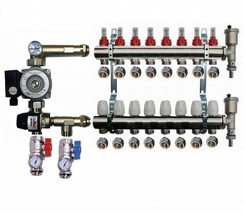
- Distribution comb with flow meters, allowing you to simultaneously connect multiple circuits.
- A separator that automatically removes air from the system. It is usually installed on ready-made mixing units from well-known manufacturers.
The main feature of the mixing unit for a warm floor is its autonomy. It works in automatic mode without human intervention, independently controlling and regulating the pressure and temperature of the coolant in the circuit.
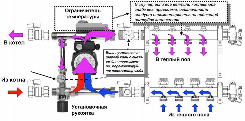
System elements
All schemes are united by ease of operation, the possibility of self-assembly, as well as the location of the main elements. The feed and “return” are located on the left side, and the collector with combs is located on the right. The differences in the schemes are in the addition of some details. More often the collector is located near the mixing unit, less often in the distance, which may be due to a lack of free space or planning features of the room.
The composition of the components depends on the material of the pipes used - made of cross-linked polypropylene, metal-plastic, corrugated stainless steel or copper.
The following elements are used in the circuit:
- Shutoff valves in the form of ball valves. They do not participate in the adjustment of the main parameters of the coolant - its temperature and pressure, but are necessary during repair work when it is necessary to disconnect individual components of the system.
- An oblique filter designed for mechanical treatment of water. It is used in the system if there is no confidence in the purity of the water used. Such a filter will not let solid particles pass into the adjustment device, thereby ensuring the correct operation of the system and extending the life of the valves.
- Thermometers providing visual control over the temperature of the water inside the circuit. Some models are equipped with a probe that is in direct contact with the coolant. Thermometers are liquid, mechanical and digital.
- The thermostatic valve is the main control element of the mixing unit. A thermostatic head is put on top of it. When the temperature of the coolant changes, the head mechanically acts on the thermal valve. If the degree is exceeded, the valve closes, and when the temperature drops, it opens.
- The bypass for the selection of cold water is a jumper, which, with the help of plumbing tees, is formed between the supply pipe and the "return". To fine-tune the coolant pressure, a balancing valve is installed on the bypass, which will ensure the optimal mode of operation of the system and its noiselessness.
- The optimal speed of the water through the pipes is ensured by a circulation pump.
Supply choke
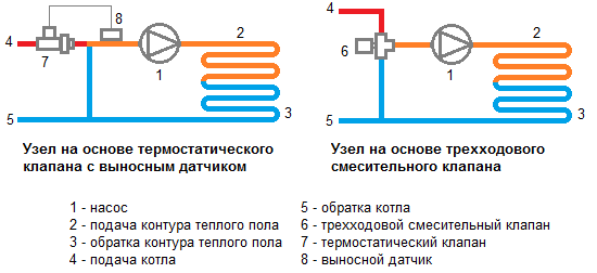 A two-way valve system is the easiest to implement. The temperature of the water entering the system pipes is controlled by a thermostatic head mounted on the valve and a liquid sensor. Opening and closing of the valve takes place thanks to the head passing hot water from the boiler to the circuit or cutting it off.
Thus, the water from the "return" comes unlimited, and hot only if necessary under the control of the valve. Thanks to this, overheating of the warm floor is eliminated and its service life is extended. The low throughput of the two-way valve provides a smooth adjustment of the water temperature, eliminating sudden changes.
Reliable and efficient valves are recommended by most specialists. But in their opinion, the supply valves will not be useful if the area of the premises is too large (over 200 m2).
Three way throttle
Unlike a two-way valve, a three-way valve mixes water of different temperatures within itself. This element combines a supply bypass valve and a bypass.The peculiarity lies in the ability to adjust the amount of hot and cold coolant for mixing, thanks to the damper located between the pipe with hot water and the "return".
Such valves have disadvantages. There is a possibility of supplying very hot water at the signal of the temperature sensor, which, due to a sharp drop, can provoke an increase in pressure in the pipes and a violation of the integrity of the circuits. The high throughput of the three-way valve can cause a sharp drop in the temperature of the water in the circuit even with a minimal adjustment of the device.
Features of setting up the mixing unit
The adjustment mechanism provides precise control of the temperature moving through the pipes of the heating system and water. This is primarily necessary to create a comfortable floor surface and conditions that extend the life of the system. Water leaves the boiler at a temperature of 60-80 degrees, and a temperature not exceeding 30 degrees is acceptable for the floor surface. The mixing unit introduces cold water into the preheated coolant, bringing it to optimal levels.
The setting is made in manual or automated mode - the servo drive will need to be purchased additionally, since it is not included in the basic package. Each circuit is equipped with shut-off valves, with which each circuit has its own settings. Thus, it is possible to set different floor surface temperatures for individual rooms or for individual sections in the same room.
Self assembly
You can collect the collector yourself. In the kit, as a rule, the manufacturer applies a detailed wiring diagram. The following types of work will be required:
- The equipment is fixed in a horizontal position on a wall or in a niche. The main requirement is to provide access for servicing and managing node elements. If the collector is not installed in a separate room, but in the bathroom or hallway, it must be masked for aesthetic purposes by installing it inside the collector cabinet.
- Heated water from the boiler is supplied from below, and a "return" is mounted from above. To install stopcocks, select the area in front of the frame, after which the pump is mounted. With its help, the “return” and hot water will be mixed, and the optimum pressure in the pipes will be maintained.
- Install a check valve and distribution comb.
- After this, it is necessary to route the pipes. Those that go to the floor are fixed on top, and pipes from the heating system are fixed at the bottom.
- When connecting the collector, components are used in the form of compression fittings, which include a support sleeve, a clamping ring and an intermediate brass nut.
- When the installation work is completed, proceed to check the tightness of the joints - crimping. To do this, using a special pump in the system, increase the pressure and leave for 24 hours. The collector assembly is fully operational if the initial pressure value for the day has not changed.
With a lack of experience with self-assembly of the collector, the following errors may be made:
- Incorrect bypass setting due to incorrect calculation of the permissible load on the circuit. Such calculations must be performed before installation.
- The absence of a separator leads to the formation of air jams in the water circuits, which reduces the efficiency of the heating system.
- Wrong selection of hot water supply point. The coolant must come from above, not from below.
- No check valve needed to prevent leakage.
If the collector was originally assembled incorrectly, subsequently eliminating errors and remaking the system would be problematic. Therefore, it is better to entrust the work to a specialist who will correctly assemble and configure the equipment.