The main problem of the heating system of a large house is the quick cooling of the coolant. This is typical of classic single pipe and double pipe systems. Their alternative is a properly designed do-it-yourself collector heating system for home heating: circuits, nodes, groups.
Installation of a collector heating system
First, you need to decide - do you need a collector water heating system? It is used only in cases where the cooling rate of the coolant in the pipes in the classical scheme is critical or in large houses. The main difference is the division of the system into several heating circuits that operate independently of each other.
Despite the positive aspects, making the right collector heating with your own hands will be problematic. Therefore, before choosing a specific scheme (or its preparation), it is necessary to take into account several important factors of the relevance of the installation:
- Large area of the house. For uniform heat distribution, several heating circuits need to be done;
- Inefficiency of mounting a tee circuit. It can affect the hydraulic distribution throughout the heating system;
- The need to disconnect individual rooms from heating. This is one way to optimize energy costs.
Given these factors, the collector heating of a two-story house is the most optimal way to organize autonomous heat supply.
If, when calculating the standard scheme, the difference between the temperatures in the supply and return pipes is more than 25 ° C, this is the first sign of the need to install distribution heating of a private house.
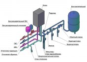
The composition of the collector heating system
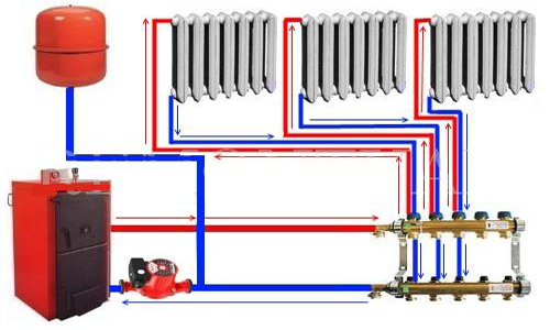
At the first stage, you need to familiarize yourself with the principle of designing an autonomous heat supply. The simplest collector heating circuit consists of a single distribution unit, to which individual lines of the system are connected.
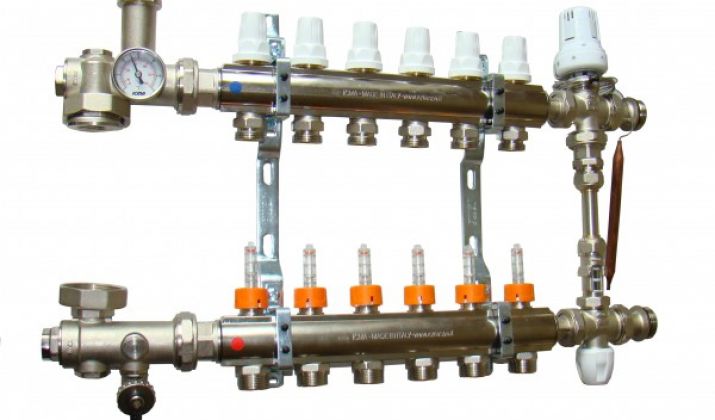
The composition includes standard components - boiler, circulation pump, expansion tank and safety group. The collector unit is installed directly next to the boiler and consists of two elements:
- Input. It is connected to the supply pipe from the heating device and distributes the hot coolant along the contours;
- Output. Return pipes from individual highways lead to it. It is necessary to collect the cooled water and its direction into the boiler for further heating.
Complex collector groups for heating are equipped with devices for regulating the volume of coolant supply - thermal heads (input) and mechanical limiters at the output.
It is best to purchase factory-made collectors. Since they are designed for certain heating parameters.
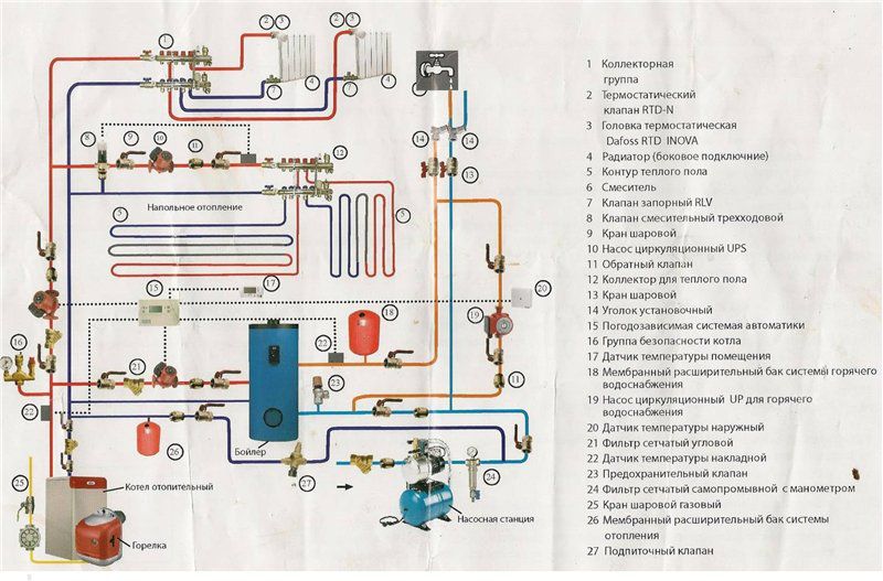
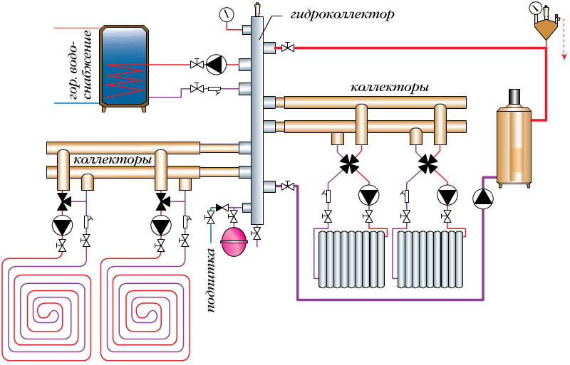
This principle is used to organize the heat supply of a one-story private house, where the capacity of the circulation pump will be enough to ensure normal pressure in the pipes. For a two-story building, two collector groups for heating can be installed. One of them will be intended for distribution over individual contours, and the second serves as the main component of a warm water floor.
For such a scheme, it is necessary to calculate the parameters of each circuit. Most often, you need to install the following additional components:
- Circulation pumps for each circuit;
- Mixing node. It is necessary to control the temperature of the coolant in the collector. The channel connects the direct and return pipes and, using a control device (two or three-way valve), flows are mixed with different degrees of heating.
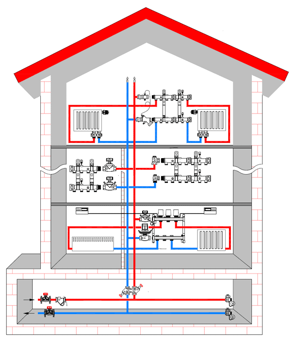
The traditional scheme of collector heating of a two-story house includes distribution nodes on the first and second levels. But it all depends on the total area of the premises and, as a result, on the length of individual highways.
You also need to consider heat transfer and optimal thermal conditions in each room.
All collectors located in residential premises must be installed in special enclosed boxes.
DIY collector heating at home
Is it difficult to make and install a heating system of this type with your own hands? It should be remembered that it is much more complicated than single-pipe or two-pipe. The main difficulty lies in the accurate calculations of each collector unit for heating.
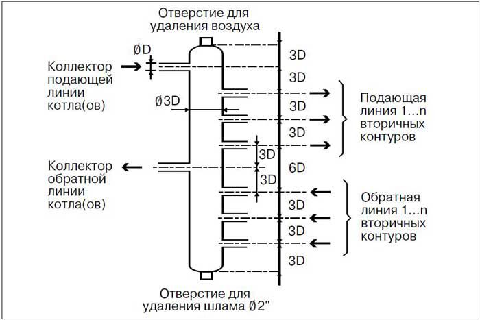
If the heating of the collector type is intended for a house with a large area and many separate highways - it is recommended to install a distribution comb with the function of a hydraulic compensator. Its difference from the standard is to connect the feed and return manifold using pipes. Its installation provides the following advantages:
- Prevents the occurrence of water hammer;
- Compensates for pressure differences due to thermal expansion of the coolant in the supply pipe;
- Automatic mixing of water flows and as a result - reduction of energy costs.
A comb of this type is mounted in the collector water heating system after a safety group. It should be located next to the boiler. If the system has additional distribution nodes, they should not be communicating. Their design is similar for underfloor heating in the collector heating of a private house.
Often, it is on them that groups of automatic control of the coolant inflow are installed. In complex collector heating circuits, the central comb is only equipped with circulation pumps and shutoff valves for each circuit.
The installation of additional distribution units is necessary so that each circuit has approximately equal length.
Calculation of collector heating
When performing a preliminary calculation of the parameters of collector heating made by oneself, one must take into account the throughput of the pipe from the boiler and the total volume of coolant. It is important that the amount of water leaving the boiler heat exchanger is equal to the incoming. Thus, it is possible to achieve uniform heat distribution in the collector heating of a two-story house.
It is also important to maintain the hydraulic balance of the system. In practice, it is recommended to use special software systems to perform the calculation. But for small collector groups for heating, you can calculate the geometric dimensions of the comb yourself. To do this, follow two basic rules:
- The diameter of the inlet manifold of the collector should be equal to the sum of the supply sections for each circuit;
- In a single-body manifold, the distance between the inlet and outlet group should be 6 nozzle diameters. In this case, the cross section of the comb housing is 3D.
This is a general calculation principle for collector-type heating. It may vary depending on the individual characteristics of the system.
The power of the circulation pumps for each heating circuit is calculated individually, depending on the length and amount of coolant in them.
Production of a heating collector
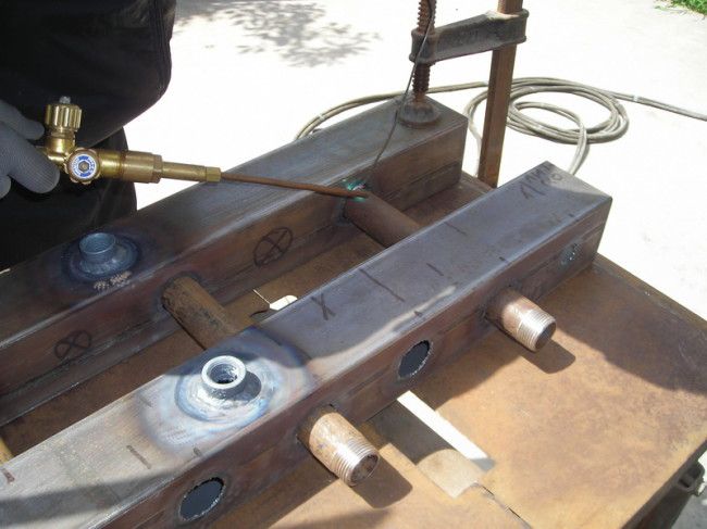
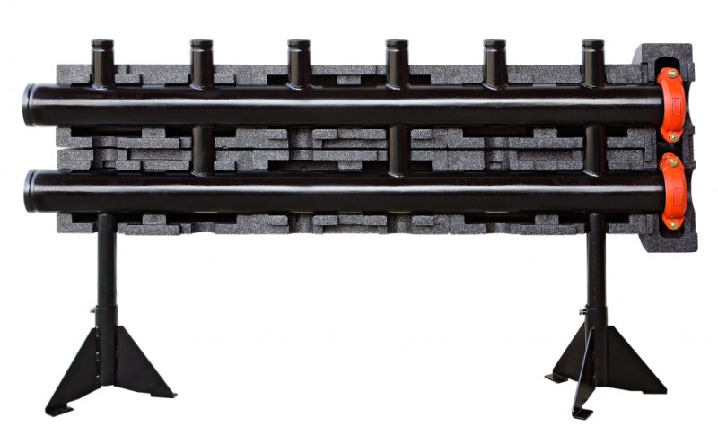
For greater reliability, the main distribution comb in the water-type collector heating system should be made of metal. To do this, you can use pipes of both square and round cross-section. The former is preferable, since the installation of nozzles in them is much simpler.
To do this, you need the following tools and materials:
- Pipe for the main heat of the heating manifold. Its dimensions should correspond to the calculated;
- Branch pipes for distribution of the heat carrier on contours. They are made of round pipes with a diameter of 16 to 25 mm, depending on the parameters of the system;
- Shutoff valves - ball valves for each circuit;
- Tools: welding machine, angle grinder (grinder), tape measure, level.
First, the main comb body is made with your own hands for collector heating. Through its surface, using the welding machine, through holes are made into which the nozzles will be installed. Then they are welded, and the tightness of the entire system is checked. To do this, you need to simulate the system. The outlet pipes are sealed, and the water supply is connected to the input of the future collector heating of a private house. Using manometers, the operating mode of the system is established and the absence of leaks in the design is visually checked. The next stage - gradually increases the pressure to the maximum design. Only after conducting such tests can collector groups be installed in the heating system.
It is best to use pipes with a wall thickness of 1 mm or more. For continuous operation, it is recommended to paint the collector surface with special paint.
Ready-made collector heating designs
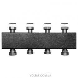
The best option for organizing collector heating in a large two-story house is to purchase factory-made combs. They differ from self-made ones in their greater reliability and accurate characteristics, which is important in any system.
However, their high cost should be considered. It directly depends on the number of connected circuits, the diameters of the inlet pipes and the geometric dimensions of the collector.
| Model | Number of nozzles | TDP kW | price, rub. |
| ELTERM KP2 | 2 | 14 | 7260 |
| Meibes v2 | 2 | 20 | 12100 |
| Meibes v3 | 3 | 25 | 22800 |
Installing these components in a collector-type heating circuit of a two-story house will help optimize the operation of the entire system. Along with this, possible heat losses must be taken into account, since the comb has a relatively large area. To minimize them, it is recommended to insulate its surface with mineral wool.
In the video material, you can read the instructions for the manufacture of the collector from polypropylene pipes: