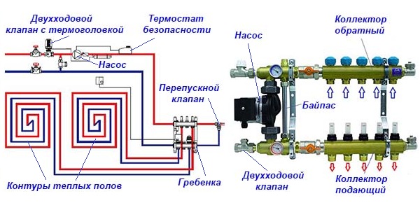
An efficient heat supply system is a productive and reliable highway. For its modernization, a heating collector is used in the form of a special unit. The comb provides the distribution of heat along the circuit, which contributes to a comfortable temperature in the house.
Distributor specifics
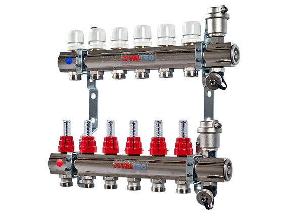
The collector is a distribution type device for the heating system, which contributes to the uniform distribution of heat. The cooled water under the influence of the circulation turns back into the boiler. The main branches thrown on the distributor function independently.
Instrument design
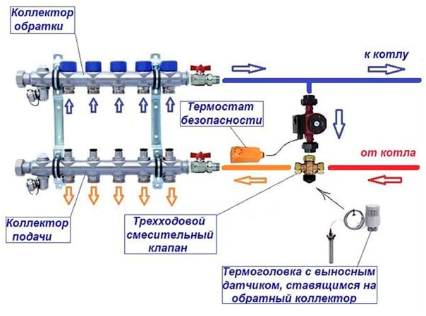
The intermediate unit consists of two parts. The supply comb brings the coolant to the communications, and the return one brings it to the heat generator during cooling. Two combs are a collector group, and on each of them you can connect one circuit or several wiring to heating devices. The pressure inside each circuit is adjustable.
Features of work
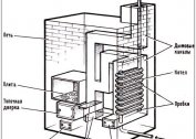
The principle of collector heating is to heat the water with a heat generator and flow it to the feed comb. Due to the large internal diameter of the unit, the liquid in it slows down the speed and is distributed over all branches.
The coolant moves to the individual circuit through connecting pipes with a smaller diameter than the distributor. Heated water can be sent to radiators, a warm floor system, ensuring uniform heating of each element.
After it enters the circuit and heat is lost, water moves through another pipeline to the distributor. The direction will be the opposite. Having reached the return comb, the coolant is sent to the heat generator.
A collector type of heating is suitable if you have a country house or a two-story cottage.
Varieties of collectors
The collector is designed for a closed circulation heating system. The device comes in several modifications.
Radiator manifolds
The water device is placed on the battery and contributes to an even distribution of water in each section. It can be connected at the top, side, bottom or enter diagonally. If you have an apartment, the lower installation will be optimal - the contours are hidden under the baseboard or floor covering.
The private house is equipped with radiator distributors on each floor. They are placed in the center of the wiring, hiding in niches or special cabinets. If the same number of rings is not output to the collector devices, an individual circulation pump is used for each outlet.
The radiator type of mechanisms has several connection features:
- Distribution branch branches form separate contours with shutoff valves;
- for underfloor heating, copper or polypropylene pipes are used;
- the connection is made using one-piece fittings;
- valves are set to adjust the amount of coolant;
- circulating sediment is in the intermediate node at the entrance to the return pipe;
- the number of pipes depends on the number of rooms connected to one comb.
One collector group should have 120 m of pipe.
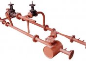
Thermohydraulic distributor
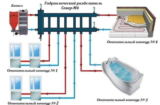
The water gun is used in a productive or branched heat supply system, to which a multi-storey type of building is connected.On one side of the link-bundle, a circuit for the heating boiler is displayed, on the second - heating radiators or underfloor heating.
Distribution hydrocollector provides:
- elimination of sharp jumps in water temperature;
- increase of operational resources in the system;
- fuel and electricity savings;
- maintaining a constant volume of water in the tank through mixing and secondary circulation;
- compensation of costs of the coolant of a secondary circuit;
- separation of the hydraulic circuit of the boiler from the secondary wiring;
- maintaining the temperature balance of heating communications.
The normal operation of the trunk with a hydraulic boom in the winter season is provided by the circulation pump of each circuit.
Solar Collector Devices
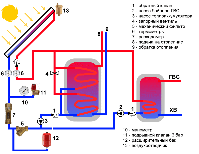
In regions without autonomous water supply or non-gasified areas, it is possible to realize heating using solar collectors. Structurally, devices are made as greenhouses capable of storing solar energy. The coolant circulates in a natural way - the circulation flows create fans of the absorbing plate.
The sun's rays are received by a dispenser in the form of a flat box. The black heat-absorbing plate accumulates heat fluxes and transfers them to the heat carrier, in which the air flow or water is involved. Innovative systems work in the direction of the sun.
Solar installations are expensive, and even in the southern regions are used as an auxiliary heating device.
Distribution manifold for heating is available with 2-12 circuits. When installing additional devices, the number of circuits can be increased.
Classification by design complexity, materials, equipment
When selecting combs, several parameters must be taken into account. Depending on the complexity of the design, the devices are simple and modernized. The first group is executed without adjusting parts and is an iron pipe with several branches and side holes for connection to the system.
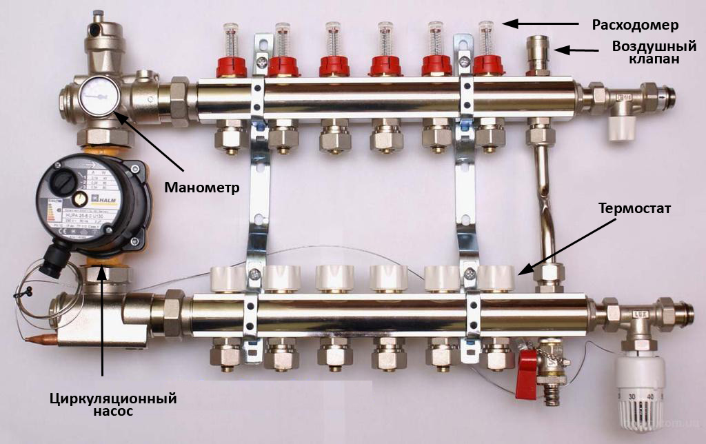
Upgraded options are equipped with:
- pressure and temperature controllers;
- sensors that regulate the flow of thermal media;
- automatic thermostats - monitor and automatically lower the system pressure;
- electronic mixers and valves to support the set temperature;
- flow meters to adjust the amount of coolant in the loops;
- automatic type air vents and automated drain valves.
For the manufacture of intermediate nodes, the following materials are used:
- long-life brass;
- stainless steel that can withstand high pressure and is durable;
- polypropylene, which is a budget material.
Upgraded manifolds are manufactured with ball valves, into which control valves are inserted. Metal models have anti-corrosion and heat-insulating coating.
Device Recommendations
When buying combs for heating, it is necessary to take into account several nuances:
- Models with collet clamps are susceptible to leaks at the valve connections. Their gasket quickly fails and is not subject to replacement.
- The system functions normally only with a circulation pump.
- To hide the collector, you will need a special cabinet or niche.
- The maximum pressure indicator depends on the block material.
- The capacity of the distributor determines the amount of coolant moving through the pipes for a certain time.
- Auxiliary elements improve the functionality of the device.
- The number of outlet pipes should equal the number of cooling circuits.
Technical parameters are registered in the product passport.
Auxiliary elements
The collector heating system is organized using additional elements:
- air vent - placed when the radiators and unit are located on the same floor;
- adapter - needed when installing an air vent with a diameter of ½ inch on a collector with a ¾ inch thread;
- corners - ensure the connection of the pipeline and the direction of the air vent up;
- faucet - needed to connect the pipe from the boiler to the distributor;
- squeezing with a union nut - used to shut off the water or gas supply and disconnect the faulty device;
- clamps with plastic dowels or brackets - will be needed to fix the assembly.
The collector connected to the warm floors is equipped with a make-up tap.
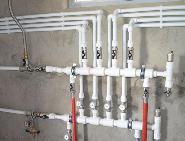
Connection and Installation Requirements
Installation and connection of the collectors is carried out during the installation of the heating system. Intermediate appliances are placed in hallways, walk-in closets or pantries. Overhead or built-in wardrobes are suitable for this. If they are not, a special niche is arranged at a height of 20-30 cm from the floor.
A unified connection scheme for the collector system has not been developed, but experts provide several recommendations:
- The expansion tank should be from 10% of the total amount of coolant.
- Installation of an individual pump on each circuit.
- An expansion tank is placed in front of the pump on the return line.
- In the presence of a hydraulic boom, the tank is placed in front of the main pump, which circulates the small circuit.
- The resource of the pump increases when located above the return.
The collector shaft is placed horizontally, which prevents airing of the system and problems with its cooling.
Installation site selection
The collector system is characterized by floor installation of pipes with the organization of an independent autonomous circuit. The distributor can be installed anywhere, hiding in a cabinet with holes for pipes on the end walls.
The room should be maintained at optimal humidity, so a pantry, dressing room or corridor is ideal. If the collector is installed in the country, it is fixed in open form to clamps or brackets.
Self assembly collector installation
With your own hands you can make a distribution manifold from several materials. You will need to select the necessary tools, make calculations, create a drawing. For the calculation, the number of circuits, the presence of underfloor heating, rooms with maximum and minimum temperatures, type of heating on each floor are taken into account.
The collector tie should have a distance of 10-15 cm, the feed and return combs are 25-30 cm apart. The diameter of the device depends on the type of boiler, but 25.4-38.1 mm will be enough.
Polypropylene appliance
It is possible to manufacture a polypropylene manifold mechanism from a pipe 32 mm in diameter and tees 32/32/16 mm. A tee is placed on one side of the device, to which an air vent is connected at the top and a drain cock at the bottom. On the other side is the exhaust pipe / valve and valve. The feed is sent to the boiler.
The outlet 16 mm in diameter is equipped with a valve. The whole structure is mounted on the wall with brackets.
Brass Knot
Homemade dispenser can be made on the basis of brass fittings and tees. The lining material will be linen tow or gremetik. After assembly, the device is tested. If connected incorrectly, it will leak.
Pipe collector
If you have welding skills, you can make a model for a large house where there is a multi-pipe wiring. The system with a hydraulic boom is made of a professional pipe 8x8 or 10x10 cm and a round pipe. Their cross-section is calculated on the basis of the thermal power of the system, the water velocity, the difference in temperature at the time of supply and return.
The wiring is separated by 15 cm, the collectors by 20 cm.The pipe is placed according to the sketch, and the wiring holes are made with a gas cutter. Small parts of the tubes are pre-welded to the block. After assembly, the mounting brackets are attached to the device by welding.
The collector type of heating provides efficient and uniform heating of the home. The system is costly and difficult to install, but pays off for the first season of operation. If you want to save money, craftsmen can make the dispenser on their own.