The market is represented by a wide variety of climatic equipment: monoblocks, split systems, breathers, chiller-fan coil systems. Everyone has a different scope and functionality. For domestic purposes, the best option is a split system.
The principle of operation of the split system
Freon is used as a refrigerant in air conditioners. In the form of gas, it enters the evaporator, where it draws heat from the air in the room. For intensive selection of thermal energy, a fan is used, which drives warm air from the premises through the evaporator.
Heated Freon enters the compressor, where it is compressed, turning into a liquid refrigerant. It passes through a condenser blown by another fan, giving off thermal energy to air and is cooled. After this, liquid freon passes through a nozzle with an expanding channel, where its pressure drops and a transition to a gaseous state occurs. Then the refrigerant enters the evaporator again.
The air conditioning system is closed and cyclic.
Design Features
The split air conditioning system differs from other types of climatic equipment in that it consists of two separate units: internal and external. The first is installed inside the room, the second on the street. The blocks are interconnected by copper tubes along which the refrigerant moves. The tubes are passed through a wall in which a hole is made previously with a punch and a diamond crown.
Indoor unit
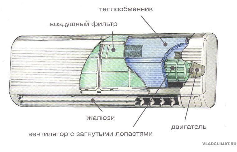
The design features of the indoor unit are that it includes an evaporator and a fan. The evaporator is a copper tube folded by a snake. Stainless steel or aluminum plates are superimposed on it in case of prolonged operation in conditions of contact with condensate. In this case, the plates increase the contact plane of warm air with the refrigerant through the metal walls of the tube.
A fan is a drum with blades connected to an electric motor. The centrifugal model is installed in a horizontal plane. The fan motor, step-down transformer and process control plateau are located in a separate section, closed from the evaporator by a sealed partition. Do not allow moisture to enter the electrical part of the unit. The purpose of the transformer is to reduce the voltage of 220 V to 24 V, which runs the process control unit.
In inverter-type air conditioners, the control unit and transformer are installed in the external unit of the split system.
The next structural element of the indoor unit is the condensate collection tray. At high temperatures in the room a large amount is formed. The tray is connected through a pipe with a drainage hose using a conventional plastic clamp. The hose through the hole in the wall is displayed on the street.
The filters retain the dust so that it does not leak to the evaporator and does not turn into a layer of dirt on it. The blades of the flap redirect the flow of chilled air.
External unit
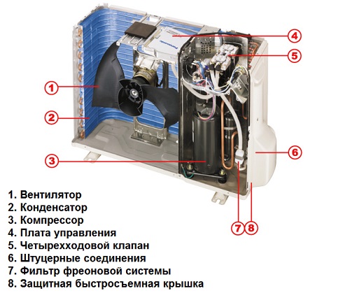
The package includes appliances of the refrigeration system:
- compressor,
- capacitor,
- fan for condenser,
- tube nozzle or TBP (thermostatic expansion valve),
- refrigerant purification filter,
- four-way valve, which ensures the operation of the split system in air conditioning and heating mode.
Types of split systems
According to the installation method, air conditioners are:
- wall mounted
- floor
- ceiling
- floor and ceiling.
Wall split systems: external and internal blocks are attached to the walls of the house. Floor, they are columned, are installed on the floor. This is a powerful technique with great cooling capacity. They are used in rooms with a large area and volume of space.
Ceiling split systems are divided into two groups:
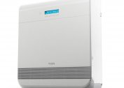
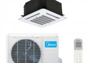
- Cassette The indoor unit is located in the space between the base ceiling surface and the suspended structure. In sight, only a decorative grille and blinds are installed, through which air is supplied to the room. The air direction can be distributed in all four directions along the ceiling surface or with a slight slope towards the floor.
- Channel. In appearance, they are similar to the cassette version. By design features, these models belong to the category of multi-systems. One external unit is installed, to which the channels from the internal units are connected. All elements of the refrigeration unit are located in the external unit, even the evaporator. From it, insulated air ducts are scattered throughout the rooms, through which the cooled air moves into the premises.
The floor and ceiling split system differs from all the others in that the indoor unit has not one row of blinds through which cold air enters the premises, but two.
One is located at the top, the second at the bottom. Mount it on the ceiling or on the floor against the wall. If it is installed on the floor, through the upper blinds, air is sent to the ceiling along the wall, through the lower - along the floor base. If installed on the ceiling, through the top - along the ceiling, through the bottom - towards the floor along the walls.
Multisplit system
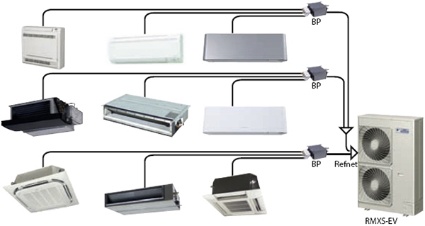
There is only one external unit and several internal ones scattered around the rooms. The latter are connected to external parallel loops of copper tubes. The MSS system is divided into two groups: fixed and typesetting.
Fixed - A fully equipped installation, precisely tailored to the compressor power. In its external unit, a certain number of ports for connecting internal units. One or two compressors can be installed in the outdoor unit.
If two compressors are included in the package, both can work on all indoor units as a single unit, or they are divided into circuits with a connection to each unit for a certain number of indoor units, then the circuits work independently of each other. Thus, it becomes possible to adjust each circuit to the required temperature regime.
Typesetting multisplit systems are up to 16 indoor units that connect to one external unit. In the latter, up to three compressors can be installed. The number of indoor units may vary depending on the number of rooms. If you need to connect 8-9 blocks inside, the remaining remaining free ports are muffled by special devices.
A multi-split system has several rather serious drawbacks:
- if the outdoor unit fails, the building is completely left without air conditioning;
- it is impossible to configure all indoor units to work in different modes;
- high price;
- complicated installation.
VRF systems differ from standard ones in that in their design there are no separate ports for connecting indoor units. There is only one from which the copper tube leaves, and other channels are connected to it through which the refrigerant moves to the internal units of the split system. Such channels can be up to 100 pieces. Thus, the freon is evenly distributed across the loops, and each unit located inside the building itself controls the temperature regime.
Additional functions
Manufacturers of many brands began to offer options for climate systems that have additional useful features:
- air humidification due to the condensate collected in the outdoor unit, which is supplied to the indoor unit through a special tube, and is sprayed with a fan;
- organization of forced ventilation due to an additional fan installed, which drives air from the street into the room;
- enhanced air filtration due to the installation of additional fine filters;
- Follow me function - the air conditioner reacts to a change in temperature in the place where the remote control is located;
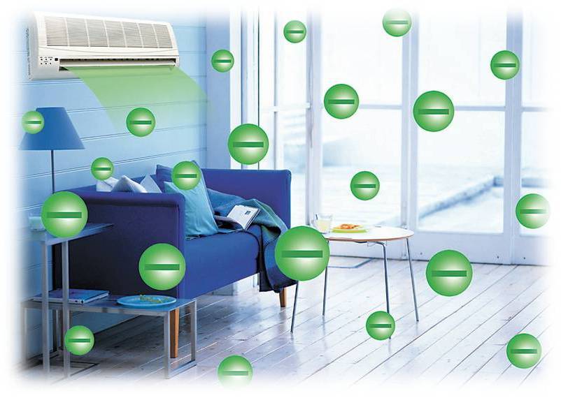
- ionization of the air charges the ions passing through the evaporator stream with a negative charge.
Regardless of whether the split system is selected: wall or floor, channel or cassette, it is necessary to strictly take into account the power of the air conditioner and the area of the refrigerated room with a ceiling height of not more than 3 m.
Here is the ratio of these parameters:
| Marking | power, kWt | Area, m² |
| 7 | 2,1-2,3 | before 18 |
| 9 | 2,6-2,9 | 18-26 |
| 12 | 3,5-3,8 | 35 |
| 14 | 4 | 40 |
| 18 | 5-5,6 | 50 |
| 24 | 6,3-7,3 | 70 |
| 28 | 8-9 | 75 |
| 30 | 8,2-9,4 | 80 |
| 36 | 10,5-11,5 | 90 |
| 41 | 12-13,5 | 100 |
| 48 | 14-15,2 | 120 |
| 60 | 16-27 | 150 |
| 96 | 28-29 | 250 |