The chiller-fan coil system is the most advanced in terms of cooling or heating the premises, but requires preliminary development of project documentation, as well as special knowledge in the field of installation of air conditioners, electrical circuits. The system is complicated, in addition it needs regular maintenance. Using equipment, you can heat not only small rooms, but also industrial facilities with large production areas, as well as residential buildings.
Before starting work, you should understand the types of fan coils, their advantages and disadvantages in order to maximize the requirements for air conditioning, heating and ventilation.
Types of fan coil installation
The schematic diagram of the fan coil provides:
- the presence of a pipeline that transports hot or cold water depending on the tasks in a certain period of time - winter, summer;
- the presence of a chiller that prepares the desired water temperature and creates a stream of fresh air taken from the street;
- internal devices (fan coil), through which the temperature in the room is adjusted.
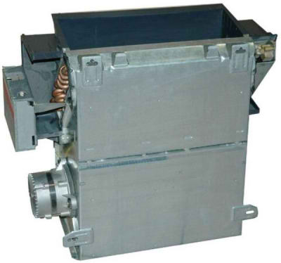
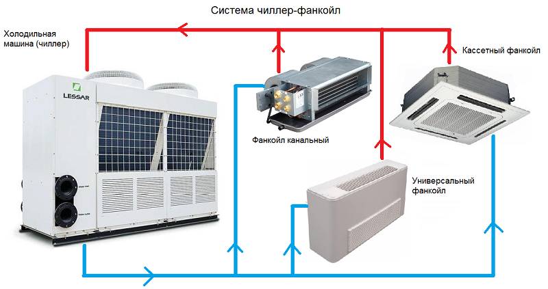 Internal climatic devices:
- Cassette Installed behind suspended ceilings. Suitable for large areas in shopping centers, industrial premises.
- Channel. Located in the ventilation shafts.
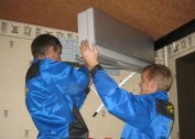
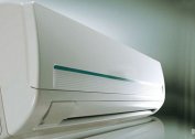
- Wall mounted. A good choice for small rooms - apartments, offices.
- Floor and ceiling. Suitable for placement under the ceiling or near the wall.
Installation of chillers and fan coils of various types has its own characteristics, as well as advantages and disadvantages:
- The channel can carry out three functions (cooling, heating, ventilation), but requires accurate calculations of the consumed air volume, expert advice in terms of installing a water heating system for the winter period.
- Installation of cassette-type fan coil units allows to save space, to condition large rooms, but requires space under the ceiling, which is allocated for the installation of the unit.
- Installation of floor-type fan coil units makes it possible to quietly cool complex rooms without affecting people's health, but requires more power and space on the floor or ceiling.
- Connecting a wall-mounted fan coil is the least economical way, but simpler.
Systems are two-pipe and four-pipe. The price of a four-pipe wiring is higher, since it simultaneously carries out heating and cooling. A two-pipe system is cheaper, but for the heating function it will be necessary to divert the pipes from the refrigeration unit and connect it to the boiler during the heating season.
An estimate for the types and cost of work is made taking into account consumables, time spent, type of equipment and its capacity
By means of a hidden connection, ducted fan coil units are mounted. The section in the ceiling must be movable to access the device.
Cassette, floor and wall units are mounted in an open way. Operation and maintenance of open-type devices is easier.
Differences in installing different types of indoor units
The scheme of the four-pipe fan coil is fundamentally different from the two-pipe scheme. In the first case, 2 circuits connected from air conditioning and heating are connected.When switching modes, additional measures are not required, the task comes from the remote control. For a two-pipe system, all fluid must be drained before manual switching. This method requires additional seasonal maintenance and making quotations in the estimate.
The way to install indoor units differs if the devices are located:
- at different levels (floors), but have the same hydraulic resistance (HS);
- at the same level with the same HS;
- with different HS, but located at the same level;
- with different HS at different levels.
Installation work must be carried out during the construction or rough repair phase of the building. After the repair is completed, final measures are taken - automatic equipment setup and installation of decorative grilles on cassette units.
Indoor units are installed in the housing or frameless method:
- Case models are installed equidistant around the entire perimeter of the room or building, regardless of the location of the rooms. This applies to a two-pipe system that works only for cooling.
- Unpacked models are installed mostly hidden. For housing units provide anti-vibration mounts.
Floor-mounted units are considered easy to install, for which it is necessary to install a drainage with the required angle of inclination in order to avoid fluid stagnation, and connect it to the mains. Correctly following the instructions or focusing on the videos, the work can be done independently.
Wall models require the help of a specialist who should:
- correctly make a harness;
- set up control devices;
- check pressure;
- make thermal insulation;
- lay pipes;
- make a pressure test;
- connect to the power supply.
For cassette models, it is necessary to provide sound insulation, vibration protection, correctly select and cut a hole in the suspended ceiling, then connect to the cold water supply and heating circuit. All connections must be checked and tested before commissioning.
Stop valves
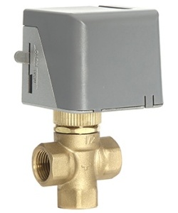
In cooling systems, three-way and two-way shut-off valves are installed. The two-way valve of the piping assembly is simpler but less reliable. In any case, it is recommended to install a three-way valve. The difference is as follows:
- When using a 2-way valve, the cooled liquid continues to flow into the fan coil when it is turned off, but this happens less intensively. Cooling continues after shutdown.
- The 3-way valve completely blocks the flow of refrigerant, therefore, when turned off, the system does not cool the room.
When mounting, it is recommended to immediately install a 3-way valve assembly. Replacing the valve during operation will require additional funds and turning off the device.
Stages of installation work
Installation of the chiller-fan coil system is carried out in the following sequence:
- The chiller is installed in the technical room or on the roof.
- The installation location is determined according to the plan. The indoor unit casing is fixed to the wall, ceiling or ventilation.
- Blocks are connected to air ducts. For channel models, valves are installed that control the flow of fresh air.
- Harness assemblies are assembled near fan coils, sensors and cranes are installed.
- Pipes are made and insulation is made.
- Drainage is discharged into the sewer.
- The system is connected to the mains.
- First start-up and leak test - pressure testing.
- Filling the pipes with coolant and final testing of the facility.
- Drawing up an act of work performed.
Dismantling is carried out in the following sequence:
- overlapping nodes near fan coils;
- disconnection from the water supply system;
- drainage shutoff;
- disconnection from the network.
If you plan to replace the fan coil units, the pipe diameters of the old and new systems are taken into account.
Installation of a fan coil electrical wiring diagram
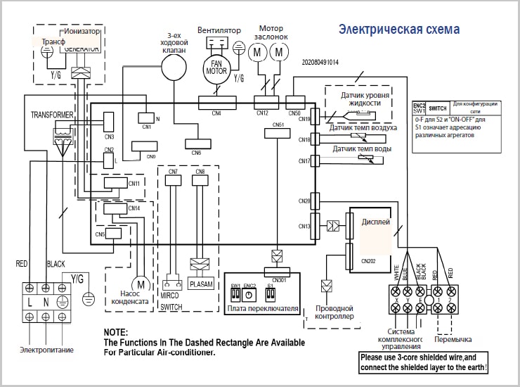
Before starting work, you need to familiarize yourself with the electrical circuit. Electrical equipment must be earthed.
Requirements for connecting fan coil units to the mains:
- use the cable as recommended in the manual;
- organize a separate power source with the necessary voltage;
- connect directly to the shield all wires, including grounding;
- the water circuit must be on the opposite side of the terminal box;
- hydraulic circuit elements must not come into contact with wires.
The unit turns on after checking the insulation. The direction of rotation of the fan impeller and the operation of the drainage pump are checked separately, if there is an electric heater.
The act is compiled according to the test results. At the same time, an agreement is signed with the company for ongoing service.
Installation of chiller-fan coil equipment must be carried out by specialists with experience and knowledge. This will improve unit performance and lower repair and maintenance costs.