Internal and external sewage systems must comply with established standards. Otherwise, the drains cannot be sent to the central highway or receiver by gravity. To ensure pressure-free operation of the collector, when installing it, the throughput of sewer pipes, their cross-section, slope, and fullness are taken into account.
The importance of making the right calculations when designing sewers
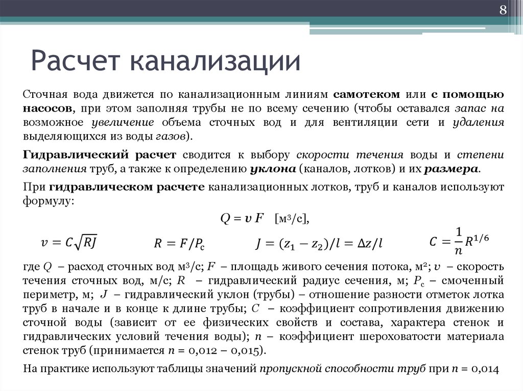 Wastewater is not just a fluid fluid of a homogeneous structure. Sewage includes impurities of various fractions and weights. Polydisperse substance, which is waste water, also contains colloids and suspensions. Sewage speed may change periodically. If liquid inclusions move faster, then heavy impurities in the form of sand, slags, etc. more often settle on the walls of pipes, forming growths and blockages. As a result, the collector becomes clogged. To prevent this from happening, at the stage of system design, a hydraulic calculation of sewer networks is carried out.
To calculate all the parameters, the estimated volume of wastewater is taken as initial data.
The main types of calculations
When performing calculations, they often use the data of SNiP 2.04.03-85 “Sewerage. External networks and structures ”, as well as recommendations from SP 40-102-2000“ Design and installation of pipelines for water supply and sewage systems made of polymer materials. General requirements".
Sewer pipeline slope
The slope is responsible for the pressure-free operation of the system and the unhindered discharge of drains into the receiver. The SNiP tables show the recommended minimum slopes for each pipe diameter:
- section 110 mm - 1 cm for each running meter of the collector;
- diameter 160 mm - 0.8 cm per meter;
- section 220 mm - 0.7 cm per meter of collector length.
For the internal part of the communication, a 1.5-2 cm slope is maintained for each running meter.
If there is a need to calculate the slope of the collector through the formula, use the following: d x coefficient, where d is the cross section of the pipeline, and the coefficient corresponds to the following values:
- 160 — 0,6;
- 220 — 0,7;
- 500 mm - 1;
- 600-800 — 1,1;
- 1000-1200 mm - 1.3.
The bias is done towards the central highway or the yard septic tank / cesspool.
Pipe cross section calculation
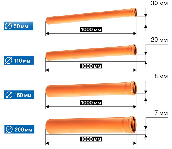
To lay pipes of the desired diameter, you can use the SNiP data. Recommended values look as follows:
- the inner part of the sewer from all plumbing fixtures - 50 mm;
- pipe from the toilet - 110 mm;
- public riser - 110-160 mm;
- the outer part of the sewage system is 160-220 mm (for the private sector and multi-apartment residential building);
- central highway and industrial enterprises - from 500 mm.
With the correct section of the collector, the fullness of the pipe will be approximately 0.3-0.5 of its total diameter.
Reservoir filling calculation
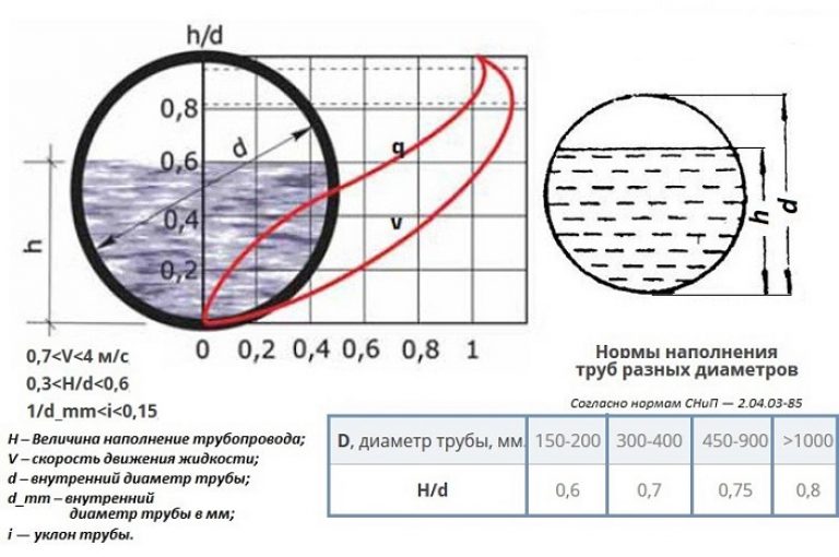 The tube fullness is calculated by the formula: Y = h / d. Here, the value of h is the maximum liquid level in the system, d is the internal section of the reservoir. Normally, the result should range from 0.3 to 0.6.
An example of calculating the level of fullness of the sewer pipe in the private sector: for the initial data, the level of collector fullness is taken within 60 mm, while the cross-section of the tube is 110 mm. According to the above formula, 60/110 and it turns out 0.55. The value is normal.
Pipe throughput calculation
At the time of designing the system, the pipeline capacity must be calculated - the estimated wastewater costs are determined. This parameter is calculated relative to the day, hours and seconds depending on the purpose of the building (residential, enterprise, etc.).The second flow rate is calculated in liters, for daily and hourly data calculated in m3.
Data for average expenses:
- Qcp.sut = p · Nр / 1000 m³ / day;
- Qcp.hour = p · Nр / (24 · 1000) m³ / hour;
- qsr sec = n · Nr / (24 · 3600) l / s.
Where:
- p - average norms of water disposal per 1 resident (in liters);
- Nр– estimated number of inhabitants.
For maximum costs:
- Qmax.sut = Qcp.sut · ksut = n · Nr · ksut / 1000 m³ / day;
- Qmax.hour = n1 · Nr · total / (24 · 1000) m³ / hour;
- qmax sec = n1 · Nr · total / (24 · 3600) l / s.
Where k are the unevenness coefficients: ksut - daily, ktotal - total.
To determine the maximum capacity of the collector, use the formula: q = aXv, where the value of a is the area of the live section of the stream, and v is the speed of transportation of wastewater.
It is customary to consider 8 m / s (metal) and up to 4 m / s (concrete, plastic) for the norm of maximum speeds for each type of pipe (manufacturing material). If the speed in fact is greater, it must be extinguished with the help of system turns or installation of overflow wells.
All hydraulic calculations must be carried out sequentially. However, more often masters use not formulas for calculations, but the data given in SNiP (in the form of tables), or use an online calculator.
Determination of effective parameters of storm sewers
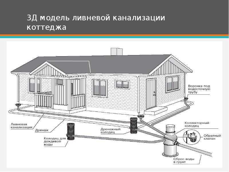 If a storm storm is installed in parallel with the fecal-household system, for the correct calculations it is necessary to take into account the following data:
- annual rainfall in the region;
- the area of the serviced object;
- type of coating (concrete, soil, tile);
- soil properties on the site;
- mass of rainwater discharged.
All data, except the last item, is taken from the local geodetic service. Using the information received, gutters are selected according to their throughput. As an example, we calculate the data on the shower trays using the formula: Q = q20 ∙ P ∙ φ
Values:
- Q - the average annual volume of storm water in the region;
- q20 - coefficient for the region;
- P is the area of the object from which water will be discharged;
- φ is the coefficient of water absorption for different types of materials.
Having determined the throughput of the tray using this formula, the gutters are selected in accordance with their technical characteristics. As a rule, this parameter is indicated on the product.
Calculation of external sewage
To design the outside of the collector, the following data is calculated:
- The length of the communication from the release from the house to the septic tank or central highway.
- Diameter of pipes (for private construction use tubes with a section of 110, 160 or 220 mm).
- Volume of effluents. The norm is 2 cubes per person per month.
- The presence of turns and overflow wells over the length of the communication.
For the device pressure-free system observe the slope. If, due to the features of the relief, the pressure section of the sewage system is mounted, a special caisson is mounted for the fecal pump and a duker is arranged. It will protect a segment of the system from the effects of subzero temperatures and stagnation of fecal matter.
Calculation of internal sewage
For the internal drainage system, the amount of required footage is calculated. On the diagram, segments of the sewer from each type of plumbing equipment are fixed. The data is summarized and the total footage of the pipeline is obtained. For accurate assembly of the system, it is important to purchase fittings, clamps, adapters, tees.
The pipeline is arranged with a slope towards the riser at the rate of 1.5-2 cm per linear meter.