Gas and its mixtures are transported through pipelines for thousands and hundreds of kilometers under excess pressure, approximately 11.8 MPa. This gas pressure is unacceptable for domestic networks, the rate drops to 1.2 MPa at gas distribution stations. At this stage, the gas is purified and receives a specific smell with the addition of volatile substances. Further, the fuel goes to equipped points, from where it comes to consumers.
Pressure classification of gas pipelines
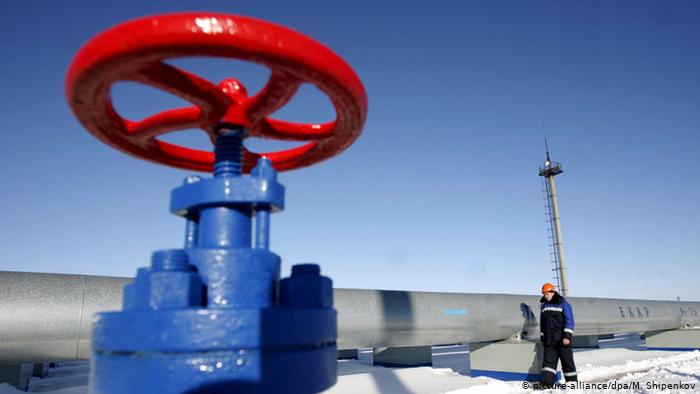
The main pipelines transmit the gas mixture over considerable distances, gas compressor units are built at some intervals to maintain the total flow strength. Reduced pressure distribution networks deliver fuel to the final destination.
Gradation of an indicator in pipelines:
- in trunk routes, pressure from 2.5 MPa and above (class 1) and 1.2 - 2.5 MPa (class 2) is provided;
- low-pressure distribution networks show up to 0.005 MPa, medium - 0.05 - 0.3 MPa, high - inclusive up to 1.2 MPa.
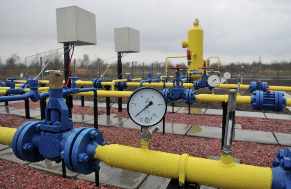
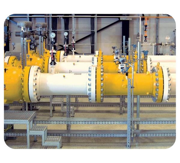
The gas distribution points are equipped with a purification filter system, pressure regulators, waste installations to remove excess volume into the atmosphere when the indicator is exceeded.
Low pressure
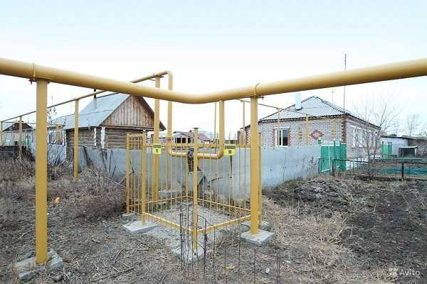
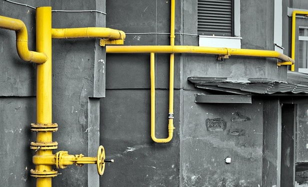
Through such networks, the gas mixture is transferred to public and residential buildings, apartments, catering facilities, boiler houses in the multi-apartment sector. The low pressure gas pipeline serves small consumers, and large facilities are not connected to such pipes. Transporting large quantities of fuel over low-pressure networks is considered wasteful in terms of economy.
The track in front of the final boiler house contains the following elements:
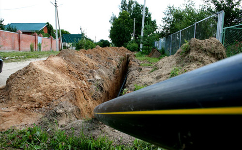
- gas supply pipes underground;
- control pipe in front of the boiler;
- electricity insulating flange;
- gate valve;
- counting unit.
The pipeline is connected through the wall, the control unit includes a sump, valves on the bypass in front of the flow meter and after, a rotational meter. A pressure gauge is placed to coordinate the crane in front of the automatic system.
Medium pressure
In large points with a high population density, pipes are laid where the gas pressure is increased. Many consumers install powerful heating equipment to balance its operation with a medium pressure gas pipeline. The pipeline transports gas to the networks of public utilities and industrial enterprises, and feed the low-pressure distribution pipelines through gas distribution stations.
The main line includes several additional nodes compared to unproductive networks:
- gas distribution station to change indicators;
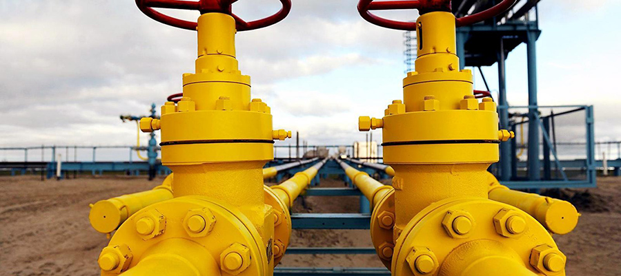
- shutoff valves, KVP and bypass;
- branch pipes from the gas distribution station to heating equipment.
Mounted flowmeter diaphragm with shut-off valve and electromagnetic automatic assembly. A gas manifold is installed, where a manometer and a purge candle are provided.
High pressure
Such pipelines are designed to transfer gas mixtures to distribution points, local distribution stations. A high pressure gas pipeline delivers fuel to production sites operating with a high pressure (according to the norm, it can be determined as at 1.2 MPa).
The main supply line for a large metropolis is arranged in the form of a ring, half-ring or in the form of a radial branching. By outlets, gas is supplied through lowering stations to medium-pressure lines.
The main pipes with a high flow rate form a closed area in which it is not allowed to carry out housing construction, to erect buildings of another type at a distance of 75 - 350 m in two directions horizontally from the axis of the route.
Natural gas supply
Natural gas fuel is supplied through pipes with a diameter up to 1420 mm. The highway is a common complex of linear parts and technological facilities. In the facilities, the gas mixture is transshipped or stored for the possible transportation of fuel by automobiles or by rail.
The condition of the pipelines is coordinated by the infrasonic or ultrasonic method, corrosion damage, pipe deformation and defects are monitored. Acoustic diagnostics is used to identify cracks in the supports of the external above-ground gas routes and to timely repair them.
The decrease in supporting stability is determined at the initial stage of failure. The methodology is simply used, does not require large expenses and shows the results of the verification.
Organization of a gas supply system
Highways pass through water bodies, swamps, therefore, corrosion protection in the form of an insulating layer is used. Metal collectors are used for the manufacture of land sections, and plastic pipes are laid under the ground and in the water. PVC resists corrosion, is a durable material, therefore, protective insulation is not required. The choice depends on the stray electric currents and the magnitude of the soil aggressiveness.
Pipelines are mounted using elements:
- supporting saddles and bearings;
- frames, bandages, stiffeners;
- flanges, valves, bends, butterfly valves, plugs.
Protective covers are used when passing underground and along the bottom of water bodies. A larger portion of the pipe is inserted into the larger collector. Gases show aggressiveness during transportation under pressure, so this gas pressure inside the route is compensated by coating with rubber, plastic, cement mixtures.
Principle of operation
Flows of combustible gases are transmitted along the mains from the production area to the places of use. The performance of the gas pipeline shows the amount of fuel for the year that is passed through the route. The indicator is calculated at the design stage according to the formulas and depends on the energy and fuel equilibrium in the area where the network passes.
Productivity may increase or decrease depending on seasonal weather, air and soil temperatures. To increase the indicator, loopings are built - additional sections parallel to the main pipe.
At the compression stations are superchargers powered by electricity.
Qualified workers are allowed to service gas networks; the state commission regularly checks the condition of pipes and supporting elements.
Categories of gas pipelines
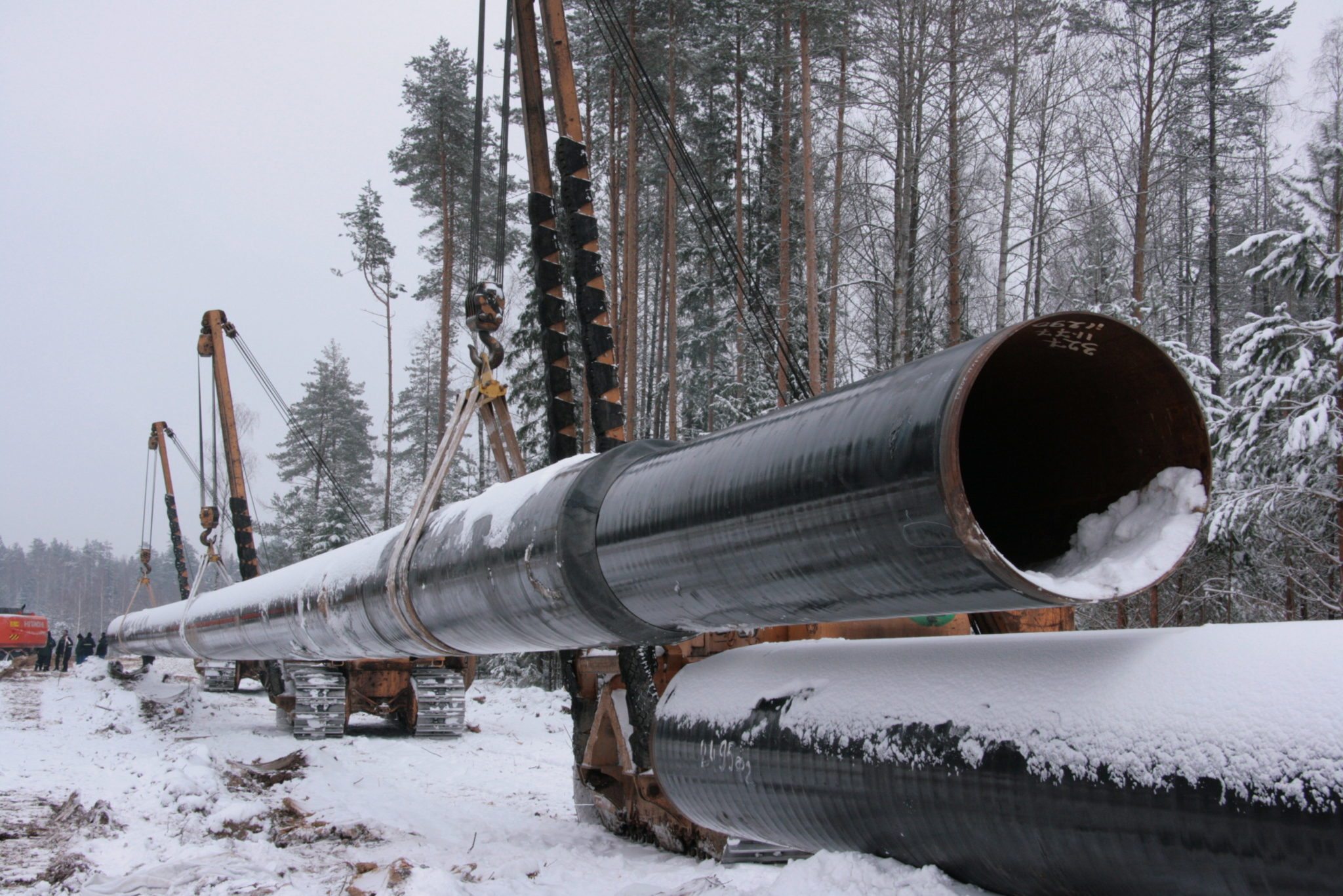
Highways are laid above ground, underground and water. Reserve networks are being built to organize transportation by transport.
Above the ground level, the pipeline runs no lower than 0.2 m. The main line is arranged with compensation sections to compensate for elongation or decrease with changing temperatures. Without such segments, the pipeline is mounted with a rigid mount and for short distances.
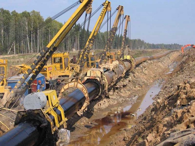
Floating trails are built in flooded areas, pass through swamps. First, a canal or trench is organized with the help of an excavator or an explosion.Pipes are connected in sections by welding, laid at the bottom or pulled through the tunnels with winches.
Underground tracks pass in frozen soils, they are isolated from cold and corrosion. Locations and turns are marked with standard elevated signs, where technical information is applied and the category of gas pipelines by pressure is affixed.
Multistage gas supply system
The concept implies a decrease in pressure on the way to the consumer in several stages. Single-stage circuits supply low-pressure mixtures; two-stage and three-stage circulate gas with low, high and medium flow rates.
Multistage routes are characterized by alternating pressure due to the long length and multiple turns on the way. Lowering steps are used before passing the route close to the settlements. The scheme is selected depending on the building density and route design.
Layout Features
Systems are ring, deadlock and mixed. The first view is a closed pipe scheme that helps to maintain one pressure for all customers connected to it. Repair is facilitated, because at this time gas is distributed by other stations located within the ring.
Deadlocks branch out to the end customer of the service. The disadvantage is the different pressure on consumers at the end sections and a gradual drop in pressure. The systems are used in domestic and intra-quarter roads.
The mixed design includes a pipe ring with branches attached to the end customers. More often used ring and combined systems.
Gas shutdown
Shut-off valves are installed in wells, the walls of which are made of moisture-resistant, non-combustible materials with high biological resistance. It is allowed to place in external enclosures with ground or wall-mounted installation.
Shutdown is provided in places:
- entrances to residential buildings, in front of outdoor gas fuel consumption units;
- entries and exits of pipes in hydraulic fracturing, branches to quarters, residential groups;
- intersections of difficult sections and water barriers, swamps, railroad tracks.
Shut-off valves and latches are mounted in an accessible place for switching of supply and repair work. The passage of pipes through the walls of the well is done in cases.