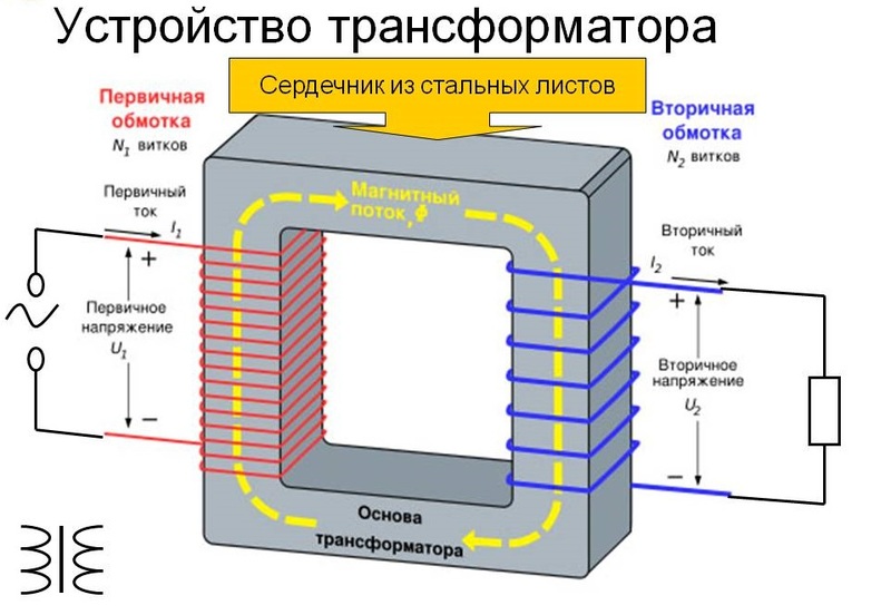
A classic voltage transformer (VT) is a device that converts one value to another. The process is accompanied by a partial loss of power, but is justified in situations where it is necessary to change the parameters of the input signal. The design of such a transformer provides for winding elements, with the correct calculation of which it is possible to obtain the required output voltage.
Purpose and principle of action
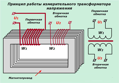
The main purpose of voltage transformers is to convert the input signal to the level specified by the tasks facing the user - when the working potential needs to be lowered or increased. This can be achieved through the principle of electromagnetic induction, formulated as a law by scientists Faraday and Maxwell. According to him, in any loop located close to another coil of the same wire, EMF is induced with current, proportional to the flux of magnetic induction that penetrates them. The magnitude of this induction in the secondary winding of the transformer (consisting of many such turns) depends on the current strength in the primary circuit and on the number of turns in one and the other coil.
The current in the secondary winding of the transformer and the voltage at the load connected to it are determined only by the ratio of the number of turns in both coils. The law of electromagnetic induction allows you to correctly calculate the parameters of the device that transmits power from input to output with the desired ratio of current and voltage.
What is the difference between a current transformer and a voltage transformer
 The main difference between current transformers (CTs) and voltage converters is their different functional purpose. The former are used only in measuring circuits, allowing to reduce the level of the controlled parameter to an acceptable value. The second ones are installed in AC electric lines and give out the voltage output used for the operation of the connected household equipment.
Their differences in design are as follows:
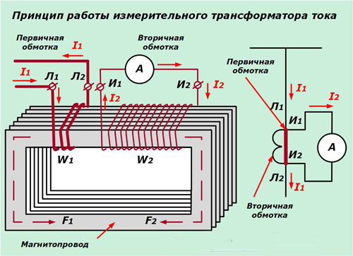
- as a primary winding in current transformers, a power supply bus is used on which it is mounted;
- secondary winding parameters are designed for connection to a measuring device (electric meter in the house, for example);
- Compared to VT, the current transformer is more compact and has a simplified switching circuit.
Current and voltage transformers meet various requirements in terms of the accuracy of the converted values. If this indicator is very important for a measuring device, then for a voltage transformer it is of secondary importance.
Voltage Transformer Classification
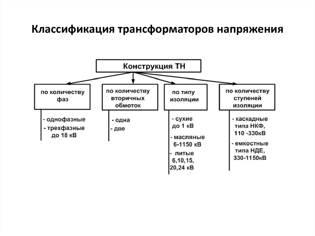 According to the generally accepted classification, these devices according to their purpose are divided into the following main types:
- power transformers with grounding and without it;
- measuring devices;
- autotransformers;
- special matching devices;
- isolation and peak transformers.
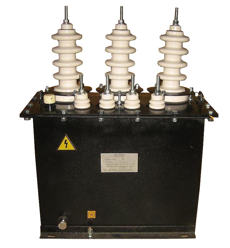
The first of these varieties are used to deliver uninterrupted power to the consumer in an acceptable form for him (with the desired amplitude). The essence of their action is to convert one level of potential to another with the goal of subsequent transfer to the load.Three-phase devices installed at a transformer substation, for example, can reduce high voltages from 6.3 and 10 kV to a household value of 0.4 kV.
Autotransformers are the simplest inductive structures having one winding with branches for adjusting the magnitude of the output voltage. Matching products are installed in low-current circuits, providing power transfer from one stage to another with minimal losses (with maximum efficiency). Using the so-called "isolation" transformers, it is possible to organize electrical isolation of circuits with high and low voltage. This guarantees the protection of the owner of the house or cottage from electric shock of high potential. In addition, this kind of converters allows you to:
- transfer electricity from the source to the consumer in the right and safe form;
- protect load circuits with sensitive devices included in them from electromagnetic interference;
- block the direct current component from entering the working circuits.
Peak transformers are another form of electrical energy conversion device. They serve to determine the polarity of the pulse signals and match it with the output parameters. This type of converters is installed in the signal circuits of computer systems and radio channels.
Measuring voltage and current transformers
Special measuring transformers are a special type of transducers that allow the inclusion of control devices in power circuits. Their main purpose is the conversion of current or voltage into a value convenient for measuring network parameters. The need for this arises in the following situations:
- when taking readings by electric meters;
- in case of installation of voltage and current protection relays in the power supply circuits;
- if there are other automation devices in it.
Measuring instruments are classified by design, type of installation, transformation ratio and number of steps. According to the first sign, they are built-in, walk-through and support, and at the place of placement - external or intended for installation in closed switchgear cubicles. According to the number of conversion steps, they are divided into single-stage and cascade, and by the transformation coefficient, into products having one or more values.
Features of VT operation in networks with isolated and grounded zero point
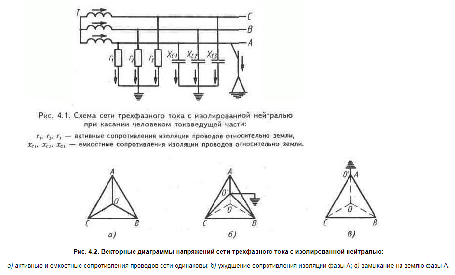 High-voltage electric networks have two versions: with an isolated zero bus, or with a compensated and grounded neutral. The first mode of connecting the zero point allows you to not disconnect the network with single-phase (OZ) or arc faults (DZ). PUEs allow the operation of lines with isolated neutral for up to eight hours with a single-phase circuit, but with the proviso that at this time, work is being done to eliminate the malfunction.
Damage to electrical equipment is possible due to an increase in phase voltage to linear and the subsequent appearance of an arc of a variable nature. Regardless of the cause and mode of operation, this is the most dangerous type of fault with a high overvoltage coefficient. It is in this case that there is a high probability of the appearance of ferroresonance in the network.
The ferroresonant circuit in power networks with isolated neutral is a zero sequence chain with nonlinear magnetization. Three-phase non-grounded VT in essence are three single-phase transformers connected according to the star-star scheme. With overvoltages in the zones where it is installed, the induction in its core increases by about 1.73 times, causing ferroresonance.
To protect against this phenomenon, special methods have been developed:
- manufacture of VT and CT with low intrinsic induction;
- inclusion in their circuit of additional damping elements;
- manufacturing of 3-phase transformers with a single magnetic system in a 5-rod version;
- neutral grounding through a current-limiting reactor;
- the use of compensation windings, etc .;
- application of relay circuits protecting VT windings from overcurrents.
These measures protect measuring VTs, but do not completely solve the safety problem. Grounding devices installed in networks with an isolated neutral bus can help with this.
The nature of the operation of low voltage transformers in earthed neutral modes is characterized by increased safety and a significant reduction in ferroresonance phenomena. In addition, their use increases the sensitivity and selectivity of protection in a single-phase circuit. Such a rise becomes possible due to the fact that the inductive winding of the transformer is included in the ground circuit and briefly increases the current through the protective device installed in it.
The PUE provides a rationale for the permissibility of short-term neutral grounding with a small inductance of the VT winding. To do this, the network uses automation, which, by the occurrence of an OZ after 0.5 seconds, briefly connects the transformer to the busbars. Due to the effect of a dead-grounded neutral during a single-phase earth fault, a current limited by the inductance of the VT begins to flow in the protective circuit. At the same time, its value is sufficient for the protection equipment to work from the hazardous area and to create conditions for extinguishing a dangerous arc discharge.