A special device is used for domestic and industrial electrical networks, ICE control and illumination. A relay is an electromagnetic or electrical type chopper with a mechanical, electronic or electrical pulse. Understanding the operating principles and design features of the device will help to independently solve a number of problems in electrical engineering.
History of creation

Some sources report that the Russian scientist P. Schilling (1830-1832) installed the relay as a ringing element on the telegraph. There is another opinion attributing the authorship of the regulator J. Henry. The American physicist created a contact type device with an electromagnetic principle of action in 1835.
If we consider the meaning of the word, “relay” from French translates as passing the baton in competitions or replacing post horses. For the first time, the regulator as an independent element was mentioned by S. Morse, who created the telegraph.
The theory of relay-type devices began to develop in 1925-1930, but after in 1936-1938. V. Shestakov, A. Nakashima and K. Shannon used mathematical logic to solve the relay problem, the theoretical base got a start.
At international symposia, the problems of the theoretical significance of the relay switch, finite state machines, were repeatedly raised. The first consultation was held in 1957 in the USA, the second - in the USSR (1962).
Relay Features
 The relay element is understood as a set of nodes and connections, which, when acting on the input, changes in the form of jumps. For this reason, to characterize the elements, criteria are used to influence the output and input:
- Operation - at the input, the effect is minimal, it grows slowly, which leads to a change in the state of the element and a simultaneous effect on the output.
- Release - reduction of the minimum input action so that the element returns to its original state.
- Return - a parameter that determines the maximum impact in the case of an increase in which the relay node returns to its original state.
- Performance - depends on the ratio of the response time to the return or release time.
An electric relay refers to an element whose type of action depends on the flow of current or conductivity.
The principle of operation of the switch
Relay - a switching device that connects or disconnects a circuit circuit when current parameters fluctuate. The device is activated when the limit of the value of the conditions (voltage or current) is reached, closing or breaking the line.
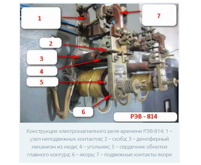
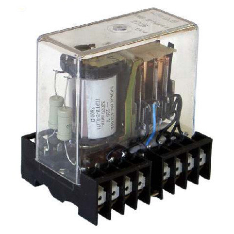
To understand the principle of relay operation, it is necessary to clarify its component parts. The design of the device includes an inductor, an armature and switching channels. When connected to a circuit in inductors with a magnetized wire, self-induction EMF occurs, i.e. phase lags behind voltage. In the process of supplying current to the coil, the element attracts an armature with contacts, which closes the circuit.
The device has two types of circuit:
- controllable - closes with an anchor at the moment of operation;
- control - through it, current flows to the coil.
High currents in the control circuit are controlled by low-current control coupling.
The electromagnetic relay device is triggered by the principle of hysteresis - activation some time after the receipt of the current pulse. The current in the coil grows loop-like, reaching the required value.Due to hysteresis, relay devices are not used for high-speed equipment.
Control and controlled contacts, permissible voltage and current parameters are indicated on the housing.
Sensitivity parameters
Sensitivity - the principle of operation of the relay, in which the device reacts even to minor deviations of indicators and quickly returns to standard mode.
Highly sensitive models perceive indicators of less than 10 mW, normal ones from 1 to 5 W, low sensitivity models from 10 to 20 W.
Varieties of Relays
To solve practical problems, types of relays are used that differ in the characteristics of action, switching on and the presence of protection.
According to the principle of work
These types of relays include:
- Electromagnetic - models of the electromechanical type, operating from the magnetic field of the winding current acting on the armature. An electromagnetic switch is neutral with a response to current parameters and polarized with a response to current magnitude and polarity.
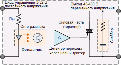
- Electronic - will work under heavy loads. The design is represented by semiconductor elements for supplying and turning off the voltage.
- Reed switches - are made in the form of a cylinder with a vacuum or filled with an inert gas coil. The reed switch is located in the center of the magnet or is exposed to the field. This variety is activated by applying current to the winding. After the formation of magnetic flux and magnetization of the springs, the contacts close.
- Electrothermal - operate on the basis of the difference in the expansion coefficient when heating bimetallic plates. The type of relay assignment is determined by the number of network phases.
Electrothermal models are suitable for production or as an electric motor.
By the type of inclusion of the sensing element
There are modifications:
- Primary - connected to the circuit of the element. They can be used without measuring transformers, cables, sources of fast currents.
- Secondary - connected via transformers with a response to fluctuations in current and voltage.
- Intermediate - are placed as an auxiliary device, amplify or transform the signals of secondary models.
The type of sensing element depends on the relay device. It can be an electromagnet, magnetoelectric, induction, electrodynamic system.
By the method of exposure
Depending on how the actuator acts on a controlled indicator, there are devices:
- direct action - the actuator acts directly on the control circuit;
- indirect action - auxiliary devices are used to influence the circuit.
As an actuating element of electromechanical devices, an active contact system is used.
Protection devices
Automation is triggered by fluctuations in resistance, power and voltage. There are relays of the following types:
- maximum current protection - MTZ are triggered when the current reaches the set limit;
- directional protection - in addition to current, power control is carried out;
- differential protection - devices respond when the voltage of the equipment changes sharply or to malfunctions in the network itself;
- remote devices - protection is carried out at standard and high frequency when a decrease in resistance or short circuits is detected;
- differential phase devices - DFZ control phases from two ends of the power line.
In domestic conditions, the use of MTZ devices of the electromagnetic type is allowed.
Designation on schemes
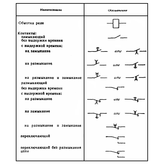
The international classifier allows you to repair or construct equipment. The scheme is distinguished by alphanumeric markers:
- a rectangle with horizontal lines on the sides, marked with the letters A and A1 - the coil of the solenoid with power leads; sometimes denoted by the letter K;
- switch contacts - stabilizer contacts;
- a rectangle with a bold dot on one contact pin or the letter P inside the figure is a polarized modification;
- rectangle with two inclined lines - the presence of two windings.
The type designations of the household relays also indicate the type of contacts, opening features and the presence of self-resetting.
Areas of use
The contact device is used to:
- electrical system control - you can put a constant current, alternating current or protection stabilizer;
- preventing the influence of voltage drops on the nodes of household appliances - the switch creates a stable type of communication;
- uninterrupted operation of industrial and production equipment;
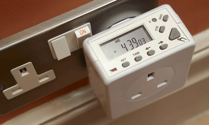
- automation of electrical appliances used in everyday life;
- gain control signals in the circuits.
The switchgear is configured by the manufacturer so that it can operate in certain situations.
Stabilizer requirements
Regardless of the method of exposure, inclusion and the presence of protection, the following technical characteristics should be taken into account when choosing:
- response time - the period from the receipt of the control signal at the input until the moment it affects the network parameters;
- switching power - allowable power limit for equipment or network;
- response power - the minimum indicator at which the device will begin to work;
- setting - a variable parameter that indicates the value of the tripping current.
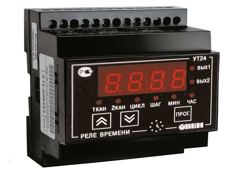
Models of modern manufacturers have a simple type of design or are equipped with microprocessors, control systems, sensors.
Observing the selection requirements and knowing the scope of the relay, it is easy to ensure uninterrupted operation of the power supply in the conditions of voltage and power fluctuations.