The phase control relay is a device whose main purpose is to protect linear circuits from overloads and short circuit. In addition, it is capable of responding to such a common phenomenon for power grids as imbalance in individual phases. As a result, this device provides comprehensive protection for operating circuits and equipment connected to them.
general information
Several types of phase imbalance relays are known, which differ in the type of housing and their design features. Despite the large number of executions and the abundance of circuit solutions, the working functions of all models are almost the same. Installing a phase monitoring relay in 3 phase circuits allows you to:
- extend the service life of electric motors;
- eliminate the need for restoration or repair work;
- reduce downtime due to malfunction of a three-phase motor and the risks of electric shock.
The phase relay installed in the linear circuits guarantees protection of the unit windings against fire and single-phase short circuit.
What is it for?
Special phase controllers are in demand in places where you often need to connect to the mains and where it is important to observe their alternation. As an example, a situation is usually considered when the connected equipment is constantly transferred from one place to another. In this case, the probability of confusing the phases of the linear stresses is very high.
In some loads, their incorrect alternation can lead to improper operation of the device and subsequent breakdown. Any unit included in such a network for a long time is very likely to fail. When operating such a device, one can easily make a mistake in assessing its condition, considering that the device needs repair.
Features of various executions and their capabilities
Two types of devices are known that are used as part of linear three-phase systems: phase current relays and voltage switches. They have a typical design, determined by the requirements of regulatory documentation. Of interest is a comparative assessment of two varieties of modular devices.
Pros of current relays
The indisputable advantages of current protective relays (TP) when comparing them with voltage monitoring devices are:
- independence from EMF, constantly arising during phase failures in case of overload of the electric motor;
- the ability to determine deviations in the behavior of an electric machine;
- admissibility of control not only of the line itself (before the branch), but also of the load connected to it.
Unlike TR, voltage control devices do not allow to realize most of the listed functions. They are intended mainly for installation in linear circuits.
Phase Failure Detection
A phase failure failure is a common occurrence due to a blown fuse or mechanical damage to the network. In similar conditions, a 3-phase motor, for example, when one of the phases disappears, continues to work due to the power taken from the remaining two. Any attempt to start it again in the absence of one of the phases will be unsuccessful.
The duration of its detection (reaction to overload) is so long that during this time the thermal protection simply does not have time to turn off the unit. In its absence, the phase wire break relay is triggered due to overheating of the motor windings.But this does not always happen, which is explained by the features of the device that is underloaded on one of the phases. In this case, the so-called “reverse emf” begins to act in it.
Reverse detection
The ability to detect phase reversal is in demand in the following situations:
- the engine is being serviced;
- significant changes have been made to the energy distribution system;
- After restoration of the power indicator, the phase sequence changes.
The need to use a phase change relay is associated with the inadmissibility of reverse motor, which can damage the mechanism itself, and also threatens maintenance personnel. The provisions of the PUE prescribe the use of this device for any equipment, including conveyors, escalators, elevators and other moving systems.
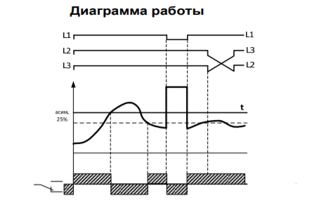
Unbalance detection
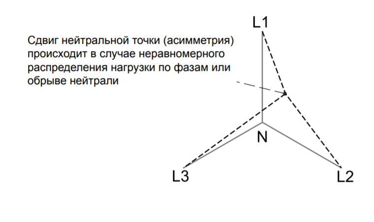
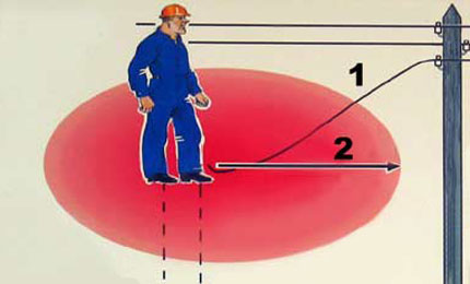
The imbalance in power networks usually manifests itself as a significant difference in the amplitudes of the phase voltages coming from the regional substation. Such an imbalance is observed in situations when the even distribution of loads across each phase is violated on the consumer side. Its presence in the system leads to a spread of currents in individual lines, which significantly reduces the service life of connected equipment (electric motors, for example).
This is explained by the fact that the so-called “adhesion” of phases in the lines of inductive loads causes additional heating of the wires and contributes to the destruction of insulation. All this is a justification for the need to install a phase protection relay in the existing electrical networks.
Connection Order
A preliminary familiarization with the features of its design will help to understand the order of connecting the relay. This process will noticeably facilitate understanding of the principle of operation, as well as the ability to configure the device immediately before starting.
Structural elements
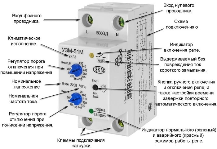
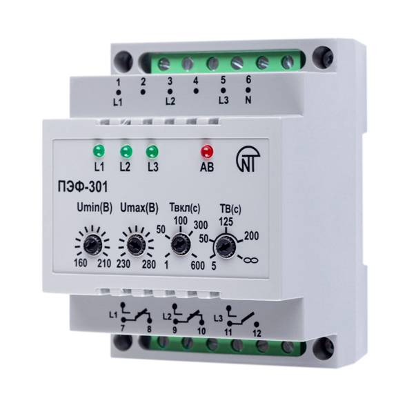
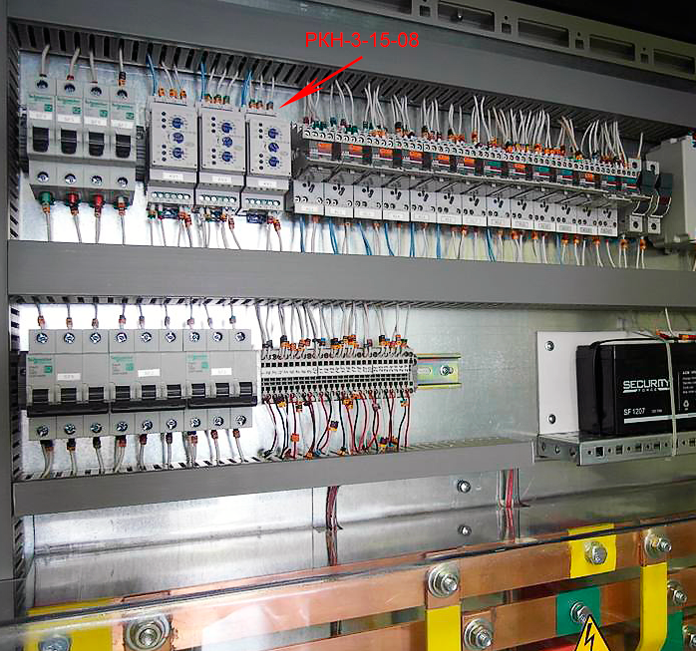
The relay housing is designed for installation on a DIN rail or on a pre-prepared level surface. The external connector allows you to connect it to the mains using standard clamps, to which copper conductors with a cross section of up to 2.5 mm2 are fed. On the front panel are the tuning controls, as well as a control lamp indicating the inclusion of the device.
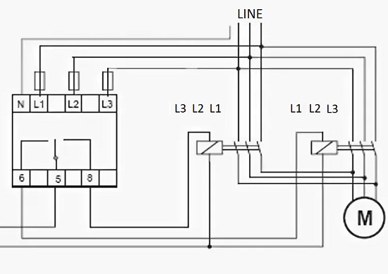
The working scheme provides indicators of the emergency situation and the connected load, as well as mode switches, asymmetry controls and time delays. Three terminals are used for connecting the device, labeled L1, L2 and L3. Like circuit breakers, they do not provide for the connection of a neutral conductor (this is not true for all relay models).
On the case of the device there is another contact group of 6 terminals used to connect to control circuits. For this purpose, a harness containing the appropriate number of wires is provided for in the wiring of power equipment. One of the contact groups controls the coil circuit of the magnetic starter, and the second - switching the equipment connected to the line.
Setting Items
Instructions for connecting and configuring assumes the presence of various circuit solutions of the device itself. In the simplest models, no more than one or two controls are displayed on the front panel. In this they differ from samples with advanced settings. In models with a large number of control elements (they are called multifunctional), a separate block of microswitches is provided. It is located on a printed circuit board located directly under the device or in a special hidden niche.
The desired relay configuration is obtained by sequentially adjusting each of the available control elements.With their help - by rotating the control knobs while simultaneously pressing the corresponding microswitch - the required protection parameters are set. The step of their installation or the sensitivity of the device for most samples is 0.5 volts.
Device marking
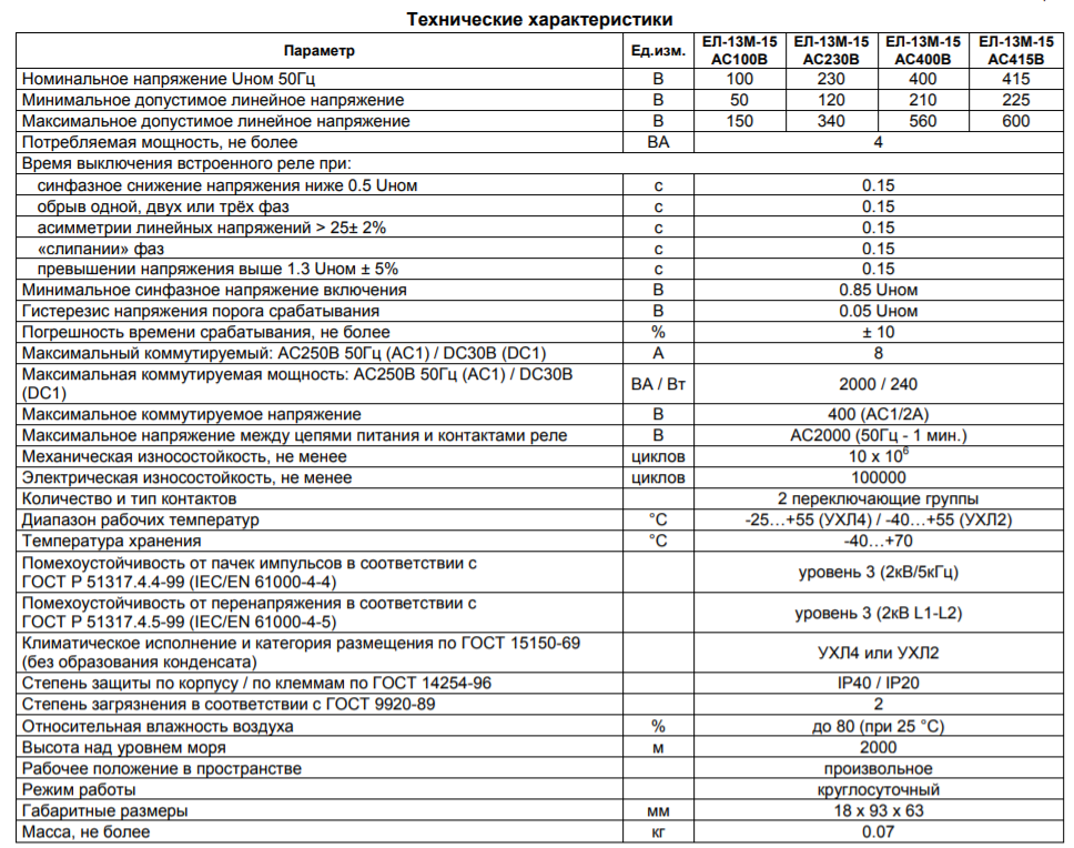
In order to mark control devices, a sequence of several characters is applied on their front or side panel (sometimes it is indicated only in the passport). As an example, a Russian-made device EL-13M-15 AC400V, designed for connection without a neutral wire, is considered. It is labeled as follows:
- EL-13M-15 - the name of the series;
- AC400V combination - allowable voltage.
Marking of imported models is somewhat different. Relay series "PAHA", with the abbreviation PAHA B400 A A 3 C is deciphered in more detail:
- B400 - operating voltage of 400 volts.
- A - type of adjustment.
- A (E) - mounting method (on a DIN rail or on a connector).
- 3 - case dimensions in mm.
The symbol "C" indicates the completion of the code combination.
Features of choice
When choosing control devices, first of all, their technical parameters are taken into account. As an example, we consider the case of selecting a model for connecting an ATS, suggesting the following procedure:
- The method of inclusion (with "zero" or without) is determined.
- The parameters of the selected device are clarified.
- At the same time, it is taken into account that when working with ATS, it will be necessary to control the break and the sequence of phases.
To control the ATS, the delay time is set within 10-15 seconds.
Familiarity with individual modifications of control devices will help the contractor to take into account the features of their functioning in specific circuits.