Users of 380 volt power circuits in the household need a passive (uncontrolled) three-phase rectifier. Knowing some of the features of an electronic device and existing rectification schemes will be very useful. This will help the owner of the power equipment to operate it more competently and rationally for a long time.
Description of rectifiers
The main difference between devices from their single-phase analogs is manifested in the following:
- the first are installed in 220 Volt lines and are used to obtain constant currents of insignificant magnitude (up to 50 Amps);
- three-phase rectifiers are used in circuits where the working (rectified) currents significantly exceed this indicator and reach several hundred amperes.
- in comparison with single-phase samples, these devices have a more complex device.
Known schemes for rectifying three-phase voltage, allowing to obtain the minimum ripple level at the output.
In electrical engineering, they are called “three-phase bridge rectifiers”, because by the method of opening diodes controlled by voltage polarity, they resemble a bridge over a river with one-way traffic. Only the direction of the electron flow in them alternates with a frequency of 50 Hz, inaccessible for cars to alternate in each direction.
Operating principle
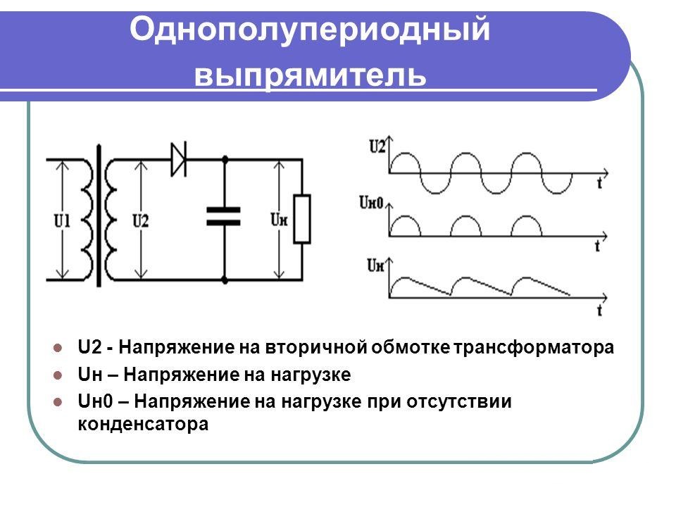
The principle of operation of any sinusoidal voltage converter is based on the rectifying properties of a special semiconductor element - a germanium or silicon diode. When alternating current flows through it, the positive half-wave freely “passes” through the working electronic transition, which is shifted in the forward direction. Under the influence of a negative half-wave, electrons encounter an obstacle in the form of a potential barrier, so that the current cannot flow through the transition.
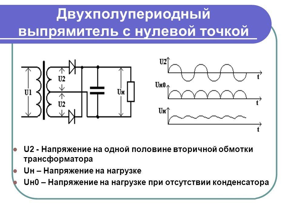
In the simplest switching schemes, an incomplete cycle of processing variable levels is used, since the second half-wave is irretrievably lost. This significantly reduces the converted power. To preserve the useful component, 2 half-wave rectification schemes were developed in which the number of diodes was increased to two.
A “full cycle circuit” may contain 4 rectifier elements, but such a circuit belongs to the category of bridge.
Half wave multiphase rectifier
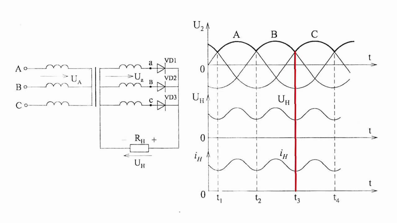
 First, it is more convenient to consider three-phase single-half-wave rectifiers that are simple to manufacture and used in simple and inexpensive converter circuits. When they are built, one powerful diode is installed in each of the phases, serving only this branch.
In total, in a half-wave sample of a rectifier device, three semiconductor diodes with loads connected to them are used. After studying the diagrams of voltages and currents obtained at the output of an electrical circuit, we can draw the following conclusions:
- the efficiency (COP) of the action of such a device is very low;
- net power is lost when processing the negative half-waves of all three phases;
- when using such devices, it is very difficult to obtain the required load characteristics.
All these shortcomings of half-wave circuits forced developers to complicate them by applying the principle of double parallel conversion.
Half-wave rectifier
 Some samples of power equipment work only with a large amount of rectified current flowing in the load.It is unable to provide half-wave rectifiers, which is explained by significant losses in them. To increase the load capacity in three-phase current circuits, two-half-wave rectifier devices containing two diodes for each phase are increasingly used.
The classic inclusion in this case is made according to the Larionov scheme, in which the rectifier device itself is named.
An analysis of the working diagrams of such a rectifier clearly demonstrates its indisputable advantages. When these circuits are used, both positive and negative half-waves are used, which raises the efficiency of the entire converter. This is explained by the fact that the three-phase structure of the circuit, together with two-half-wave rectification, provides a six-fold increase in the pulsation frequency. Due to this, the amplitude of the output signal after smoothing capacitors increases markedly (in comparison with a half-wave rectifier), and the power transmitted to the load increases.
Bridge devices
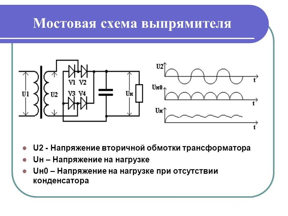 The "three-phase bridge rectification circuit" allows even more to increase the efficiency of converting AC voltage to DC. It is more convenient to present this switching method in the form of a combination of two half-wave zero-point circuits in which the odd diodes form the cathode group, and the even ones form their anode combination. In a three-phase bridge circuit, two branches of the processing of half-waves of different polarity are actually combined into a single system.
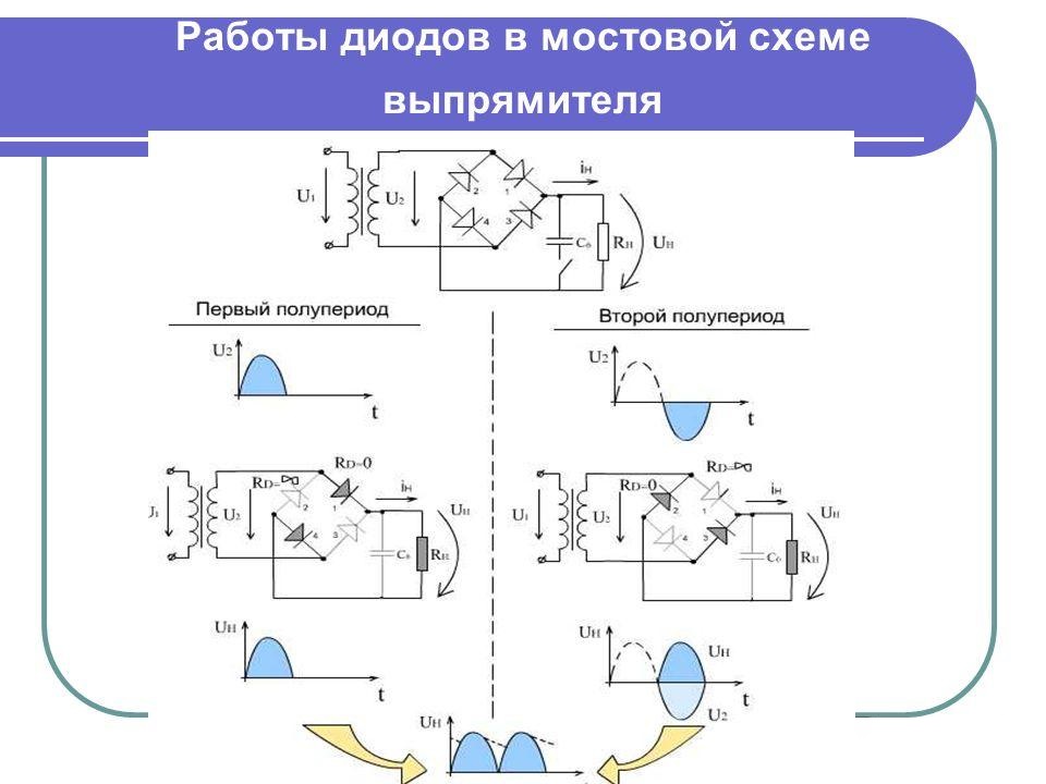
The principle of operation of a three-phase bridge rectifier is easiest to imagine like this:
- when an alternating potential acts at its input, for each half-wave, two of the four diodes open, which are switched on as if in mirror;
- in the first case, the positive half-wave of the input voltage is straightened, and in the second, negative;
- as a result, the output of such a crossover circuit always has a plus at one pole of the bridge, and a minus at the other.
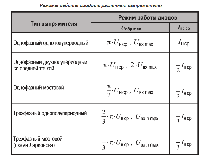
Both in three-phase rectifier bridges and in half-wave circuits at diode junctions, a part of the input voltage is lost (at each diode - no more than 0.6 Volts).
The total loss per cycle (positive and negative) in a three-phase bridge will thus be 1.2 Volts. Developers of rectifier equipment always take these losses into account and, in order to obtain the required power at the output, a little overstate the input parameters in advance.
Voltage diagrams or diagrams of bridge circuits are the best confirmation that this method of connecting diodes to the rectifier circuit provides maximum energy transfer. At the same time, small voltage losses at the junctions are most often compensated for by better filtering in the secondary circuits.
Features of a three-phase bridge and its construction options
 Bridge circuits of three-phase rectifiers have options for improving the parameters of the device. They can be improved by introducing additional valve elements. They install 6, 9 or even 12 rectifier diodes, connected according to the "star" or "triangle" scheme.
The more phases (or pairs of diodes) used in the rectifier circuit, the lower the level of ripple of the output voltage.
As an example, consider a device with 12 rectifier diodes. One of the groups of 6 pieces is included in this case according to the "star" scheme with a common zero point, and the second - in a triangle (without earth). Given that the rectifiers are connected in series, the potentials at the output of the system are summed, and the ripple frequency in the load turns out to be 12 times the network value (50 Hz). After filtering, the voltage supplied to the consumer is characterized by a higher quality.
Comparison of single-phase and three-phase devices
 When comparing three-phase rectification schemes with single-phase analogs, it is important to note the following points:
- the first ones are used only in 380 Volt power networks, and the second variety can be installed in both single-phase and three-phase circuits (one for each phase);
- 380 Volt rectifiers can convert large power and develop significant currents in the load;
- on the other hand, it is somewhat more difficult to make a three-phase rectifier on its own, since it consists of a larger number of components.
The calculation of a three-phase rectifier will also be more difficult, since in this case the vector components of the currents and voltages are taken into account. This is due to the fact that in the 380 Volt circuits the phase parameters are shifted relative to each other by 120 degrees.
Understanding the essence of a three-phase rectifier is a snap. To do this, you need to familiarize yourself with the basics of the operation of valve devices and analyze the electrical circuit for their inclusion. Knowledge of the principle of operation of rectifier devices will help the user to use it more effectively in everyday work.