Each room has several power points for the operation of various devices. The technique works by means of electric current, which is conducted through specially installed cables - conductors. The quality of the voltage, stability and safety of use depend on the quality of the network elements and the connection method. There are two main methods - parallel and serial. Each has its advantages and disadvantages, which are better to familiarize yourself with beforehand.
The main electrical quantities of the circuit
 To understand the nuances of connecting and connecting electrical conductors, you need to find out the main points and values of current circuits. An electric chain is not an independent device, but a combination of several mechanisms and elements used to conduct electric current. Key Details:
- sources: transformers, electrical installations, batteries, generators, batteries and others;
- receivers: directly equipment - lamps, motors, heaters, inductors, similar;
- intermediate links: wires, devices.
The main values by which the properties of electrical circuits are established are voltage, resistance and current. In conductors, electricity represents many electric charges moving in a given direction. By current in the network is meant intensity or force, which is measured by the number of charges simultaneously passing through the cross section of the conductor.
Voltage is the amount of electrical energy that is needed to move one charge from one point to another. It is expressed in Volts. Resistance is the forces acting on the flow of electric charges during the movement of conductors. It is recorded in Omaha.
The interdependence of electrical quantities
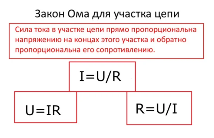 The relationship between the quantities in the electrical circuit is explained by the laws of electrical engineering. The first is Ohm's Law. Discovered and confirmed by George Simon Om back in 1827. It consists in the fact that the magnitude of the current intensity is directly proportional to the magnitude of the voltage in the conductor cable. Ohm's law allows you to quickly analyze the electrical circuit and evaluate its capabilities, limits.
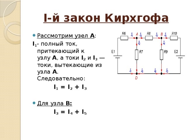
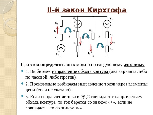
In addition to the basic rule in electrical engineering, the Kirchhoff Laws are used. One says that the sum of the currents at the input is equal to the sum of the currents at the output. The second is that the sum of the EMF is equal to the sum of the voltage drops on the internal elements of the electrical circuit.
Kirchhoff's laws make it possible to establish the relationship between the currents passing through the nodes of the electrical wiring and the currents at the entrance to the loop circuit. Analysis and calculations are carried out according to the following algorithm:
- The total number of branches and nodes of a particular electrical network is set.
- In a random order, conditionally positive directions of currents in the wiring are selected, the corresponding marks are put on the diagram.
- To obtain the equation, positive directions of loop traversal are marked in free order;
- An equation is compiled according to the rules of Kirchhoff to obtain a result.
The solution of the constructed problems will allow you to determine the number and value of currents in a particular electrical circuit.
Using the laws of Ohm and Kirchhoff, electricians evaluate the state of the network, its performance and power. In practice, live formulas are rarely used. Practicing electricians are guided in the characteristics more freely.It may seem difficult for novice editors to have one-time orientation in all indicators and relationships, it is more convenient to have some auxiliary materials at hand.
Parallel connection of conductors
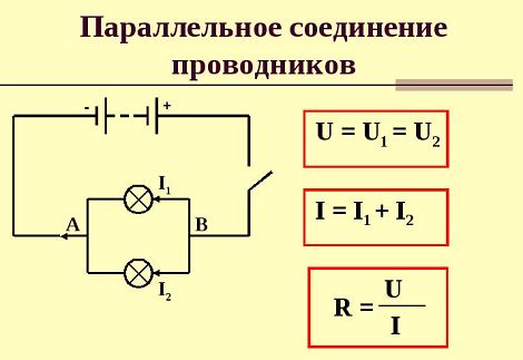 The connection of cables in the wiring is possible in three options: parallel, sequential, mixed. The first method - parallel connection - is that the conductors are interconnected at the start and end points. It turns out that the loads from both ends merge, and the voltage is obtained in parallel. In one electrical network, two, three or more cables can be connected in parallel.
To check the intensity of the current flow with this connection, two bulbs are connected to the parallel network (the indicators should be identical - resistance, voltage). In order to test and control the result, an ammeter (a device that measures current) is connected to each. The third device is powered on the network as a whole to see the indicator on the entire network. Additional items - power, key.
After the circuit is assembled, the key activates the power and compares the results on ammeters. In general, the indicator should be equal to the sum of two connected to the lamps. In this case, it is believed that the system is working properly - voltage in parallel is supplied in normal mode.
If a short circuit occurs in one area, the bulbs will remain operational. The current flows in a closed circuit from two sides. Repair will be necessary in any case, but the light and power will remain.
If you connect a voltmeter to the specified system, you can evaluate the network resistance indicators. An equivalent indicator will indicate the level of network resistance at the same current intensity.
Series connection of conductors
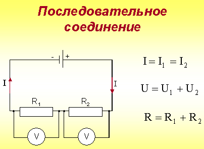 The following connection diagram - a serial connection of conductors in a circuit - involves inserting each device in the order of priority (one after the other). The intensity of the current passing through each battery (bulb, device) will be the same. In this case, the voltage during series connection is the sum of the voltage indicators from each section (obtained by the total).
Resistance value may vary. If the load changes at one of the places of serial connection, the resistance level will also change. As a result, the current indicator changes.
The main disadvantage of such an electric circuit is that if a failure occurs in one of the sections (breakdown, short circuit), the elements following it will cease to function. The connection diagram is clearly presented in the usual New Year's garlands - when one contact breaks or a wire in any place, the rest stop working.
When connecting the wires in series, the end of one cable is connected to the beginning of the next. The key difference between the electric circuit is the absence of branching, one electric current passes through the sections. In this case, the potential difference of the resistor is explained by the total voltage for each individual resistor (contact, section, power point).
Laws of series and parallel connection of conductors
The rules explaining the "behavior" of conductors in series and parallel connections include the basic laws of electrical engineering and some features. The latter are not always obvious to beginners, so they are dismantled as separate laws. When working with conductor circuits, the following should be considered:
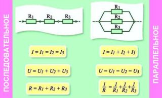
- Series connection implies the same current indicators in each section.
- Ohm's law for each type of connection has its own meaning. For example, with a sequential switching method, the voltage will be equal to the sum of the voltages of all sections of the network.
- The total resistance of the electric circuit with alternating connection will be equal to the sum of the values of the resistance of the elements, does not depend on the number of conductors and power points.
- A parallel method - the voltage of an electric circuit is equal to the voltage on each individual element, it does not add up, but remains the same.
- The current strength for this connection method is determined by the sum of the values of the currents of the connection sections.
These laws are used to build the wiring diagram in the room.
In order to optimize the load, not to create excessive stress in individual parts, check the optimality of each type of connection in a particular situation.
Mixed conductor connection
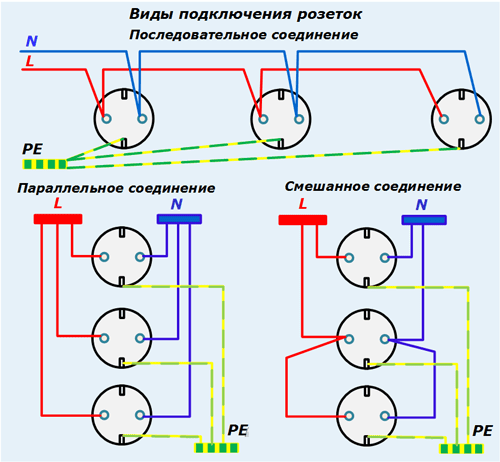
As a rule, in electrical wiring, parallel and serial connections are used simultaneously. This method of connecting wires is called mixed or combined. When constructing the initial power supply scheme in the room, where the number and location of power points (sockets, switches, transformers) are indicated, the need for each type of connection in different areas is taken into account.
Electrical wiring rarely consists of simple elements. Often it turns out a complex scheme of many different sections and connections. Therefore, when drawing up a plan, it is important to understand the advantages and disadvantages of the types of wire connections in order to optimally use each. To do this, the scheme is divided into sections and in each case, choose your own method of inserting wires.
How to choose a connection type
The consumed electric energy in the apartment comes from the common house electrical panel. The amount of current consumed is measured by a counter. The lead-in wire to the room has a large cross-section and is the main "supplier" of electricity to the apartment. The following are taken with lower rates, since the load on them is reduced due to distribution.
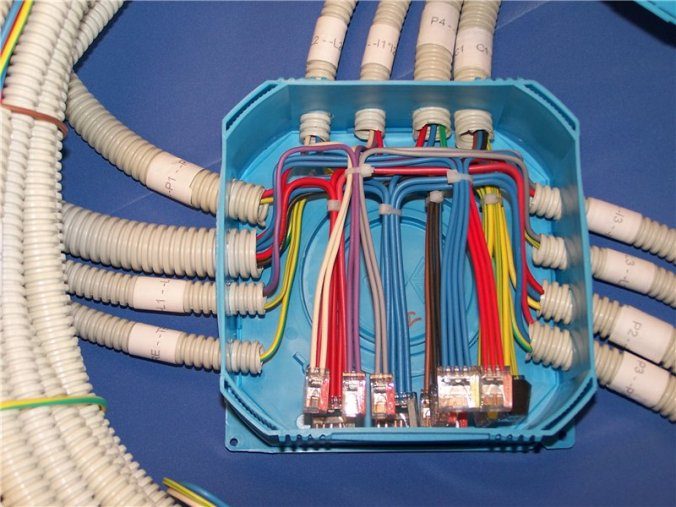
The main cable is inserted into a special junction box, from which they are wired into rooms and bathrooms. At this stage, it is necessary to determine what type of wire connection will be used: serial, parallel, combined.
There is no definitive ban on building wiring in an apartment in one way or another. However, the practical application of each circuit, disadvantages, advantages, and opportunities should be considered.
The most suitable and often used option is a mixed wire connection. A cable is supplied from the common panel to the distribution box, then several distribution nodes (in each room) are closed in a parallel network. Further, in the rooms, the power points are connected in series.
The sequential inclusion of elements can significantly save on materials during wiring. Therefore, despite certain disadvantages, the method is used in small rooms. In small areas, it is easier to identify the place of failure than in the apartment as a whole.
Parallel connection visually represents a ring of wires. If a failure occurs in one section, the current does not stop flowing - supply takes place on the other side of the circuit. However, for this type of connection, a significant amount of cable is required, which is not always convenient.
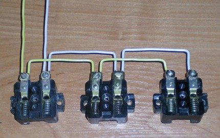
In some situations, it is advisable to use only a serial connection of wires. For example, in long corridors it is necessary to turn on and off several lighting devices at once. A loopback connection is optimal in this situation. The difficulty of replacing a light bulb or a node in the area depends on the type of wiring and decoration.
When drawing up a diagram of the electrical network in the apartment and buying bulbs for lighting, it is important to take into account the voltage level.A series connection means that the voltage is divided evenly by the number of bulbs. For example, if you install two in a row, the value on each will be 110V, not 220V.
When buying a secondary home, you should make sure that the technical documentation contains a valid wiring diagram. Having a plan will allow you to safely make repairs and correctly connect new power points, lamps.
Electricians in complex circuits always use both types of connections. On the one hand, this approach reduces the total amount of consumables. On the other hand, it allows to realize in each concrete room the advantages of both methods of cable insertion. With an independent connection, you need to understand in detail the aspects of each type, if possible, consult with the master. Otherwise, there is a high probability of incorrect connection and malfunctions.