All users are familiar with conventional light switches, made in the form of a keyboard device, mounted directly on the wall. To connect the switch if it is necessary to replace it with a new product or after repair, you will need to familiarize yourself with the design and existing types of keyboard devices.
Design and purpose

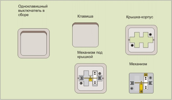
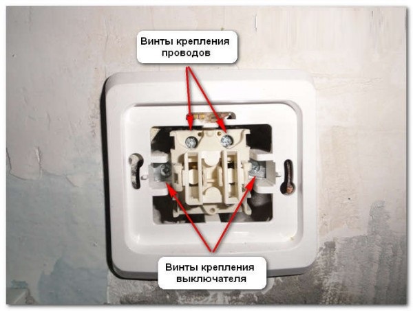
The single-key lighting switch is simple in design and consists of the following main parts and assemblies:
- a plastic case, designed in the form of a frame with a switching mechanism fixed to it;
- two steel terminals for connecting lead-in and lead-out conductors;
- decorative cover and a wide key (in some models, a control button is provided instead of it).
On the plastic frame there are two fixing ears with holes designed to fix the device in the mounting box or directly on the wall surface.
The circuit-breaker terminals have screw clamps, which securely fix the conductors leading in and out to the side of the distribution box.
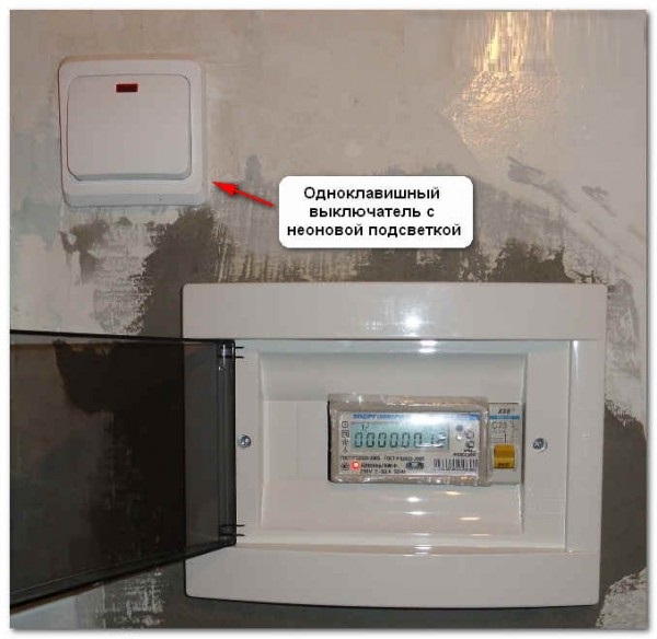
The purpose of the key switch is the switching of lighting circuits - turning the chandelier or lamp on and off. The scope of its application is not limited to one household sphere, since such a switch can be installed in rooms of any categories.
Types and Placement
Single-key household products are available in the following versions:
- for outdoor installation and exclusion;
- for internal installation;
- in the form of modular designs.
By the degree of protection against moisture and dust, these products are divided into devices of increased tightness and conventional performance.
Light switches for indoor installation are used with a hidden method of wiring the conductors in the apartment. In the latter case, they are placed under the plaster or in the cavities of the frame walls.
For outdoor installation, the switch housing is mounted directly on the wall or on a wood / plastic lining.
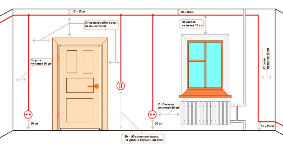
Before connecting a switch with one key to an existing network, you will need to familiarize yourself with the rules for its safe installation within the room. According to standards adopted back in Soviet times, the device relies on a distance of at least 1.6 meters from the floor. This restriction was adopted for reasons of ease of use of the instrument, located approximately at eye level. Today, these stringent requirements have been removed; according to the new rules, the electrical switch can be placed in the following areas:
- on the wall surface from the side of the door handle at a height of about one meter from the floor;
- at a distance of at least 0.6 meters from the door to the bathroom or shower room;
- at a distance of at least 0.5 meters from gas pipes and other hazardous lines.
Switches with a light bulb control from the lace can be installed in the area under the ceiling.
Modular devices or “wire switches” are mainly used in office premises, as well as in industrial and commercial areas. These products are intended exclusively for installation in plastic cable ducts. Special-purpose appliances are installed in rooms with high humidity: bathrooms, basements, attics and other utility rooms.
Rules for connection and preparation for installation
According to the provisions of the PUE, the connection of a single-key switch to any network is carried out only in the gap of the phase conductor.
It is strictly forbidden to install it in the section of the zero bus. Otherwise, there is a danger of electric shock when repairing a chandelier, for example.
Before connecting the switch to line conductors, you will need to thoroughly prepare for this event.
Preparatory procedures
At the preparatory stage, the following operations are carried out:
- A location suitable for the installation of the device is selected. The basic requirements are convenience and safety.
- The circuit diagram of the connection of the switch is drawn in all details.
- A set of tools and materials is being prepared, without which it is impossible to do when carrying out installation work.
The place for installation is selected in full accordance with the requirements of current standards, and when drawing up a wiring diagram for the circuit breaker, the direction of connection must be taken into account.
On the bottom and top of the casing are marked arrows pointing inward and outward. They mean the places of entry of the phase conductor going from the linear automaton and the conclusion of its continuation.
 In the absence of arrows, one should be guided by other signs indicating where the switch is up and down. The wire from the circuit breaker is always routed from below. For indoor or outdoor installation and subsequent connection to the network, the following set of tools and materials will be required:
- flat and Phillips screwdriver;
- mounting side cutters;
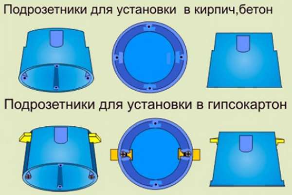
- installation box for flush mounting;
- Socket for open installation.
Also, prepare an insulation tape and a set of additional fasteners.
When preparing a tool, it is important to pay attention to another crucial detail. To install the switch in a closed way, you need a drill with a special drill nozzle, which experts call the “crown”.
Connection Instructions
The various switch connection schemes are similar to each other, but differ in some important details. Therefore, it makes sense to consider three different options related to the external and internal installation of products, as well as with the switching method in the junction box.
Outdoor device installation
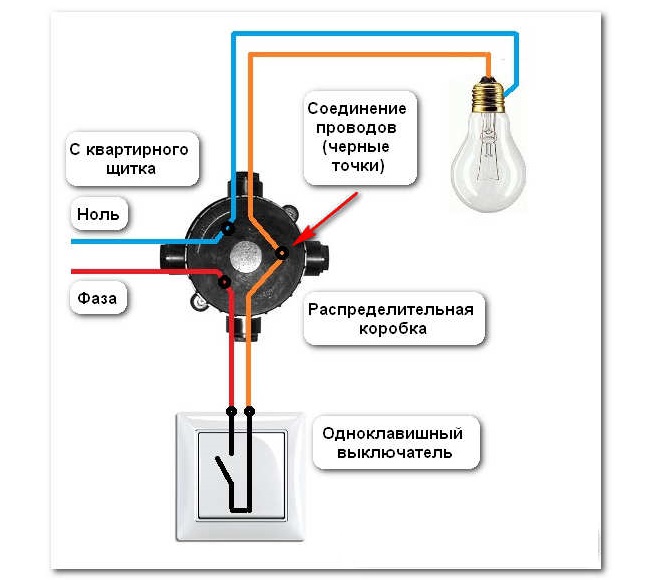
The simplest way to connect a single-key switch on the wall surface is implemented according to the classical scheme. The phase conductor that is withdrawn from the machine is connected to the lower terminal, and the one that leaves the top contact goes directly to the light source. In this situation, it does not matter how both of these conductors are laid: on the surface of the walls or secretly.
A connection is considered correct when the device itself is installed in a phase wire break. This rule is equally true for all options considered.
Flush Mounting
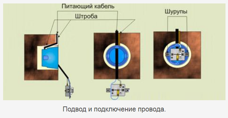 In the case of hidden cable laying in the thickness of the walls, the switch housing is located in niches specially designed for this, and the wires are led to it through a plastic installation box. Upon completion of their connection with the product terminals, the case with the box is recessed in a wall niche and fixed there with special screws. After that, it remains to close the switch frame with a decorative cover and set the switch key to its place.
To make all these operations as soon as possible, you will have to use ready-made conductors and niches left from the old switch. If the length of the aluminum conductor sticking out of the wall is not enough to connect, you will have to increase it using a piece of copper conductor and a miniature transitional terminal block.
Connection via junction box
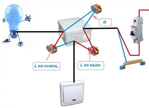
To open the switch through the distribution box, you will need to do the following operations:
- The withdrawn phase conductor is laid to the corresponding contact of the distribution unit.
- After fixing it, another wire extends to the light fixture.
- The neutral conductor is usually not required to be laid, since it is laid in advance in the thickness of the walls or ceiling to the second terminal of the illuminator.
All procedures for opening a single switch are similar to the operations already described previously.
How to connect a single-key device to two bulbs

When considering the connection scheme of a single-key switch to two lamps installed in different places, you need to pay attention to the following details:
- One conductor is diverted from the upper terminal of the device towards the junction box.
- From it towards each of the illuminators stretches its own separate phase wire.
- In conclusion, it remains to conduct the disconnection inside the box itself, after which the two outgoing to the light bulbs will be connected using a jumper.
This method is applicable only when two illuminators are located nearby - in the same room with a common junction box.
To lay the wires to the second lighting device, it is not necessary to prepare the strobes in the walls and ceiling. You can use the usual plastic cable duct laid along the same route.
If there is an earth bus in the apartment wiring, the corresponding wire is connected to the lamp housing. In its absence, the ground terminal remains unused.