Payment of electricity consumed is based on the readings of electric meters. Installation of devices is mandatory for all users and rooms using the appropriate resource. There are several options and models that differ in the types of joints and the level of ultimate load. The connection of current transformers to a three-phase meter is carried out in different ways - the choice of circuit depends on the room and voltage.
General requirements
Current transformers are equipment that is installed to reduce (convert) the indicator to a level normal for the operation of accounting and control mechanisms (meters).
In other words, these devices (manufactured by Mercury, Lenelectro and others) are installed in areas with significant power when direct connection is not possible due to high currents. Direct connection without an appropriate fuse leads to the burning of magnetic coils and equipment failure.
As a rule, the connection of current transformers involved masters of special installation and commissioning organizations. In large industries, there are separate workshops and laboratories.
First of all, a technical audit is carried out - an external inspection, a test for operability and maximum power. In addition, the tangent of the inner insulating wire and resistance are measured. Based on the data obtained, a connection diagram is selected, markup is made, the required number of holes is drilled.
Principle of operation of measuring transformers
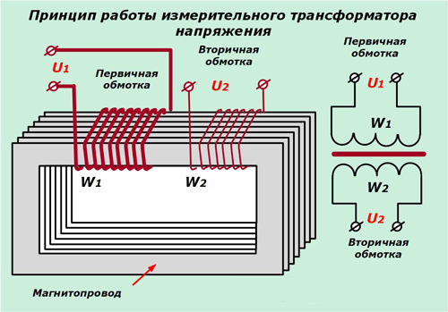 The internal structure and method of operation of current transformers is based on simple principles, the circuit is simple. The primary winding of the coil is connected in series so that the phase load current flows. After that, the induction of the electromagnetic field arises, which goes to the secondary coil. Three-phase transformers are embedded in the latter.
To reduce, a transformation coefficient is used, due to which a smaller amount of electricity is supplied to the secondary winding. This ensures the normal operation of the meter, and the output indicators must be multiplied by the number of the coefficient to get the true value of the consumed voltage.
Thus, the transformer mechanism converts the high voltage at the input to an acceptable voltage for the meter. The equipment operates at a frequency of 50 Hz and a current of 5A. for example, if the device has a load limit of 100A, the output data is multiplied by 20 (100 divided by 5).
Thanks to the adapters, the meters are protected against voltage surges, short circuits, and overloads. Moreover, if a transformer burns out, it is easier to replace it than an electrical meter.
When connecting, it is worth considering some disadvantages. The most common option - does not take into account the starting current value of the meter. In this case, the counter simply will not be able to start work.
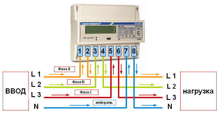
Non-observance of polarity during connection is another frequently admitted error. At the input of the primary coil there are two terminals - one for phase L1, the other for load L2. The measuring coil winding is also equipped with two terminals (I1 and I2). The cable must be connected to the appropriate contacts, after calculating the maximum load.
If the microcontacts and wires are not correctly connected, a short circuit will occur.This can lead to the failure of devices, fires.
Wiring diagrams
Electrical meters and transformers are connected taking into account safety requirements and operating rules, as well as the features of the device itself. The minimum installation temperature is + 5˚ Celsius. Otherwise, the correct technical connection will not work - devices operating with voltage and currents do not tolerate low temperatures.
If you want to connect a transformer on the street in the cold season, you need to build a special cabinet - insulated and sealed. The device itself is usually installed at a height of 1-1.7 meters.
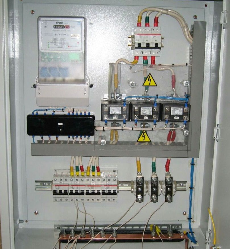
Installation of a counter with current transformers
It is not always possible to measure the consumed electricity through a meter connected directly to the power network (into a wall outlet). In circuits with a voltage of 380 volts and current limits greater than 100A - respectively, and consumption rises to 60 kW - installation of a measuring current transformer is required. The wizard calls this connection indirect, but this method gives the most accurate data. In addition, there are two more methods:
- semi-indirect;
- star.
The first is used in industrial enterprises and large factories with a power consumption above 0.4 kW and a current of more than 100A.
The “star” scheme, in turn, can be complete and incomplete. For a full star, devices with a uniform load distribution and a symmetrical current flow are suitable. The transformer is installed on all phases, and the relay winding is connected in the shape of a star.
Incomplete - a two-phase two-relay circuit with the formation of a part of the star. This circuit quickly responds to short circuits (except grounding), and there is also the possibility of installation on interphase shields.
Installation of a multi-turn meter
A three-phase transformer inclusion meter is used in multi-wire networks. With multi-turn connections, the primary winding of the coil is replaced by cable. The device controls the movement of current through the secondary winding. Otherwise, the transformer operates on the same principle as equipment of a different type.
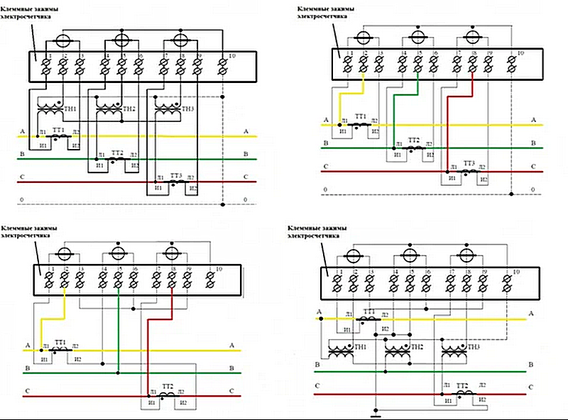
Ten wire circuit
This connection method is suitable for use in powerful power circuits, the operation of which is provided by transformers. The isolation of the galvanic type is suitable for industrial and domestic needs and guarantees the safe operation of the equipment. Terminal connection sequence (first to last):
- phase input (A);
- measuring circuit of the phase mechanism, input;
- measuring drive, output (A);
- terminal, phase, input;
- measuring circuit of the phase mechanism, output (V);
- phase, output (V);
- phase input (C);
- circuit, phase measurement - input.
The ten-wire circuit does not require a power outage when replacing the meter and performing other work. Current circuits are reliably grounded, which eliminates the possibility of accumulation of unwanted potential. Each phase is assembled independently of each other - in the event of a failure on one, the others will continue to work.
Seven-wire circuit
Such a connection scheme has several advantages and some disadvantages. Slightly different from ten-wire. It is convenient to work with the meter - there is no need to turn off the system completely when working with the panel, metering devices and transformers.
Owing to the grounded current circuits, dangerous potentials do not accumulate at the outputs of the secondary windings, which often lead to short circuits and equipment combustion. A test box is connected to the common network, which allows you to safely disconnect the power circuit.
The seven-wire method is one of the obsolete, rarely used. Electrical installers of professional companies do not recommend connecting in more modern ways.
Combined Circuit
This scheme is significantly different from the previous ones. Combined current transformers are connected via special jumpers (the path is obtained from L1 to L2).
This scheme of connecting the transformer to the meter does not comply with the updated safety rules in force today. Therefore, the use of combined chains is prohibited - both in production and in domestic conditions.
Other connection systems
In addition to these, there are other schemes for connecting the meter to the transformer. The use of a test block in a connection, according to Clause 1.5.23 of the Electrical Installation Rules, is necessary when activating a standard meter. This is an additional equipment that allows you to shunt and disconnect current circuits, activate the meters without reducing the voltage load. Another point is the ability to phase readings.
The basis of the connection through the test box is a ten-wire circuit. The difference lies in the installation between the meter and the transformer design of the adapter block with the necessary protective and distribution functions.
Electricity metering with current transformers
 Correct accounting of energy consumption is required. Intentional or accidental errors will lead to inspections, penalties, dismissals, in especially serious cases when financial obligations after recalculation are unbearable - to the closure and bankruptcy of enterprises.
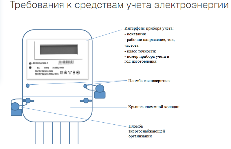
An electric meter is the main device that shows the current energy consumption. Modern models give readings with greater accuracy, it is possible to configure several modes of operation (for example, different metering in the daytime and nighttime - tariffs differ). Masters recommend installing electronic equipment, not induction. The former are much more expensive, but reflect more accurate data.
The first thing you pay attention to is the number of phases in the network. Counters and transformers must have the same number of phases with the mains.
Three-phase devices are allowed on single-phase networks (not vice versa), but they are several times more expensive. A similar option is used if such a transformer is available.
An important point is the accuracy class of transformers. Most of the facilities use 2.0 marking, which is enough for medium production and domestic needs. For large-scale factories, substations, buildings, a higher class is required - 1.0. The best option if the designation is supplemented by the letter S, which means the maximum accuracy of the device.
Electricity is a product for the use of which a certain fee must be paid. For different situations - industry, apartments, social facilities, other - separate rates are provided. To correctly pay for the energy consumed, you need the correct and accurate metering.
If the meter is working properly, sealed by the appropriate services, its testimony is transmitted to the organization with which the contract for the supply of electricity was concluded. Further, in accordance with the electric meter, payment is calculated.
For large facilities using high voltage, installation of transformers is necessary. Otherwise, it will be impossible to use electric meters and take readings, keep a record of current consumption.