It is difficult to do without LEDs in the design of electronic equipment, as well as in the manufacture of economical lighting fixtures. Their reliability, ease of installation and relative cheapness attract the attention of developers of household and industrial fixtures. Therefore, many users are interested in circuit solutions for turning on the LED, implying a direct supply of phase voltage to it. Non-specialists in the field of electronics and electricians will be useful to learn how to connect the LED to 220V.
Technical features of the diode
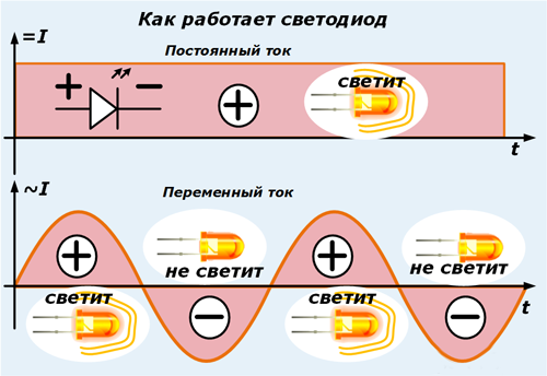
By definition, an LED, the circuit of which is similar to a conventional diode, is the same semiconductor that transmits current in one direction and emits light when it flows. Its working transition is not designed for high voltages, so just a few volts are enough for the LED element to light up. Another feature of this device is the need to supply a constant voltage to it, since with alternating 220 volts the LED will flash with a mains frequency (50 Hz). It is believed that the human eye does not respond to such blinks and that they do not harm him. But nevertheless, according to current standards, it is necessary to use constant potential for its work. Otherwise, special protective measures must be applied against dangerous reverse voltages.
Most examples of lighting equipment in which diodes are used as lighting elements are connected to the network through special converters - drivers. These devices are necessary to obtain a constant 12, 24, 36 or 48 volts from the source mains voltage. Despite their wide distribution in everyday life, situations are not uncommon when circumstances force one to do without a driver. In this case, it is important to be able to turn on the 220 V LEDs.
LED pole
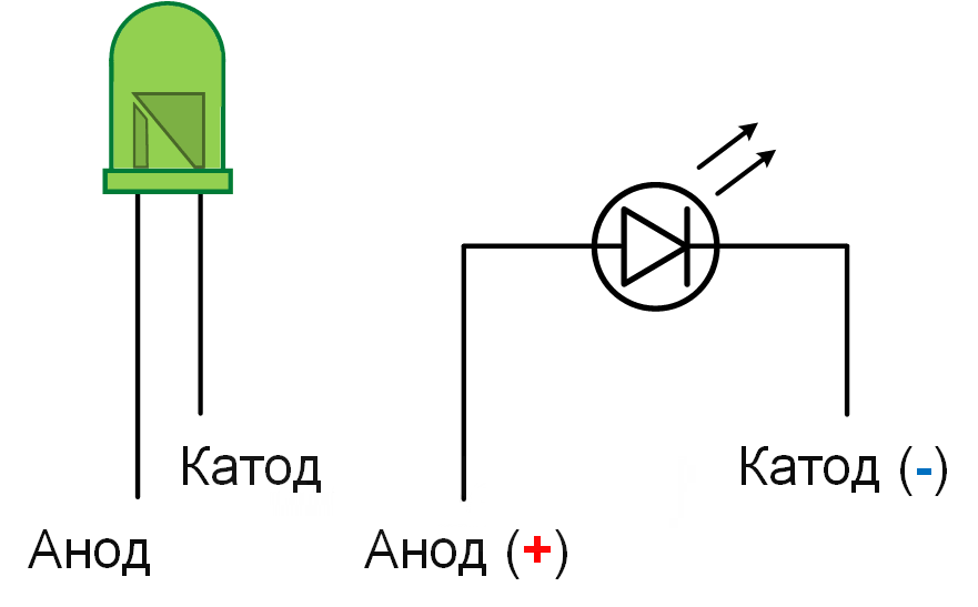
To get acquainted with the wiring diagrams and the wiring of the diode element, you need to find out what the pinout of the LED looks like. As its graphic designation, a triangle is used, one of the corners of which is adjoined by a short vertical strip - in the diagram it is called the cathode. It is considered output for direct current flowing in from the back. A positive potential is supplied from the power source and therefore the input contact is called the anode (by analogy with electronic tubes).
Industrial LEDs have only two outputs (less commonly, three or even four). Three methods are known for determining their polarity:
- a visual method that allows you to determine the anode of an element by a characteristic protrusion on one of the legs;
- using a multimeter in the "Diode Test" mode;
- by means of a power supply with a constant output voltage.
To determine the polarity in the second way, the positive end of the measuring cable of the tester in red insulation is connected to one contact terminal of the diode, and the black negative to the other. If the device shows a forward voltage of the order of half a volt, the anode is located on the plus end. If an infinity sign or “0L” appears on the display, the cathode is located at this end.
When checking from a 12 Volt power supply, its plus should be connected to one end of the LED through a 1 kΩ limiting resistor. If the diode lights up, its anode is located on the plus side of the power supply, and if not, on the other end.
Connection Methods
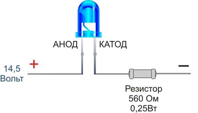
The simplest approach to solving the problem of an unacceptable reverse voltage for a diode is to install an additional resistor in series with it, which can limit 220 volts. This element has received the name of the quenching one, as it “dissipates” excess power on itself, leaving the LED necessary for its operation to 12-24 Volts.
Serial installation of a limiting resistor also solves the problem of reverse voltage at the junction of the diode, which decreases to the same values. As a modification of series connection with voltage limitation, a mixed or combined circuit for connecting 220 V LEDs is considered. In it, a series resistor has several parallel-connected diodes per resistor.
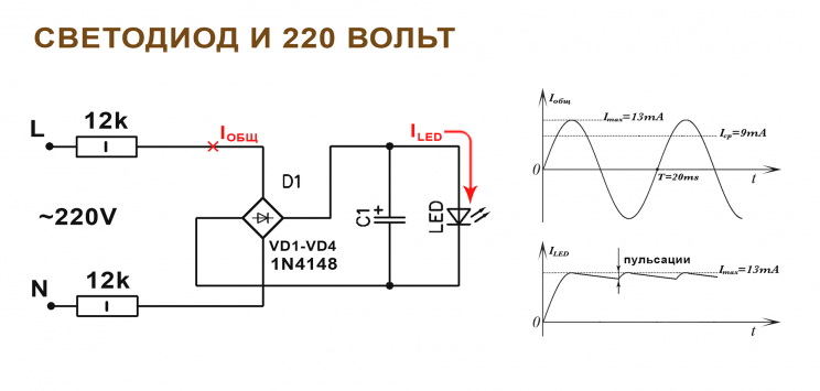
The LED connection can be arranged according to a scheme in which a conventional diode is used instead of a resistor, having a high reverse breakdown voltage (preferably up to 400 volts or more). For these purposes, it is most convenient to take a typical product of the brand 1N4007 with a stated indicator of up to 1000 Volts in the characteristics. When it is installed in a serial chain (for the manufacture of a garland, for example), the reverse part of the wave is rectified by a semiconductor diode. In this case, it performs the function of a shunt protecting the light element chip from breakdown.
LED bypass with a conventional diode (anti-parallel connection)
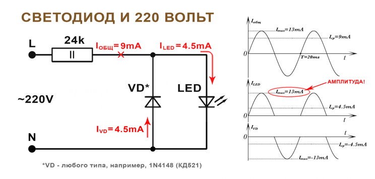
Another common version of the "neutralization" of the reverse half-wave is to use, together with a quenching resistor, another LED that is switched on in parallel and towards the first element. In this circuit, the reverse voltage "closes" through a parallel-connected diode and is limited by the additional resistance connected in series.
Such a combination of two LEDs resembles the previous version, but with one difference. Each of them works with "its" part of the sinusoid, providing the other element with protection against breakdown.
A significant drawback of the connection scheme through a quenching resistor is the significant amount of unproductive power consumed idle on it.
This is confirmed by the following example. Let a damping resistor of 24 kOhm and an LED with a working current of 9 mA be used. The power dissipated by the resistance will be equal to 9x9x24 = 1944 mW (after rounding - about 2 watts). In order for the resistor to work in optimal mode, it is selected with a P value of at least 3 watts. On the LED itself, a very insignificant part of the energy is consumed.
On the other hand, when using several series-connected LED elements, it is impractical to install a quenching resistor for reasons of the optimal mode of their glow. If you choose a very small resistance value, it will quickly burn out due to the large current and significant power dissipation. Therefore, the function of the current-limiting element in an alternating current circuit is more natural to perform on a capacitor, on which energy is not lost.
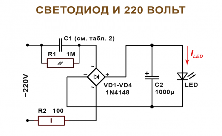
Capacitor limitation
The simplest circuit for connecting LEDs through a limit capacitor C is characterized by the following features:
- charge and discharge chains are provided that provide operating modes of the reactive element;
- one more LED is needed to protect the main from reverse voltage;
- To calculate the capacitance of the capacitor, an empirically obtained formula is used in which specific numbers are substituted.
To calculate the value of the nominal C, you need to multiply the current strength in the circuit by the empirically derived coefficient of 4.45. After this, the resulting product should be divided by the difference between the limiting voltage (310 Volts) and its drop on the LED.
As an example, consider connecting a capacitor to an RGB or conventional LED diode with a voltage drop at its junction equal to 3 Volts and a current through it of 9 mA. According to the considered formula, its capacitance will be 0.13 μF. To introduce an amendment to its exact value, it should be taken into account that the current component affects the magnitude of this parameter to a greater extent.
The empirical formula established by experiment is valid only for calculating the capacities and parameters of 220 V LEDs installed in networks with a frequency of 50 Hz. In other frequency ranges of supply voltages (in converters, for example), a factor of 4.45 needs to be recalculated.
The nuances of connecting to a 220 volt network
When using various schemes for connecting the LED to the 220 V network, some nuances are possible, taking into account which will help to avoid elementary errors in switching electrical circuits. They are mainly related to the magnitude of the current flowing through the circuit when power is supplied to it. To understand them, you need to consider the simplest type of lighting device for decoration, consisting of a whole set of LED elements or an ordinary lamp based on them.
Considerable attention is paid to the features of the processes occurring in the circuit breaker at the time of power supply. To ensure a “soft” switching mode, it is necessary to solder a quenching resistor and an LED indicator in parallel to its contacts, indicating the on state.
The resistance value is selected according to the methods described previously.
Only after a switch with a resistor in the circuit is the tape itself with chips of LED elements. Protective diodes are not provided in it, so that the value of the quenching resistor is selected from the calculation of the current flowing along the circuit, it should not exceed a value of the order of 1 mA.
The LED indicator light in this circuit performs the function of the load, further limiting the current. Due to its small size, it will glow very dimly, but this is enough for the night mode. Under the action of the reverse half-wave, the voltage is partially suppressed at the resistor, which protects the diode from undesirable breakdown.
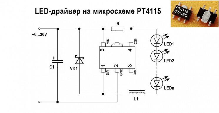
220 volt ice driver circuit
A more reliable way to power the LEDs from the network is to use a special converter or driver that lowers the voltage to a safe level. The main purpose of the driver for the 220 volt LED is to limit the current through it within the permissible value (according to the passport). It includes a voltage driver, a rectifier bridge and a current stabilizer microcircuit.
Driver option without current stabilizer
 If you want to assemble a power supply device for LEDs from 220 V yourself, you will need to know the following:
- when using the output stabilizer, the amplitude of the ripple is significantly reduced;
- in this case, part of the power is lost on the microcircuit itself, which affects the brightness of the glow of the radiating devices;
- when using a high-capacity filter electrolyte instead of a branded stabilizer, the pulsations are not completely smoothed out, but remain within acceptable limits.
With self-production of the driver, the circuit can be simplified by replacing the output microcircuit with an electrolyte.
Connection Security
When working with a circuit for connecting diodes to a 220 Volt network, the main danger is a limiting capacitor connected in series with them. Under the influence of mains voltage, it is charged to a potential dangerous to humans. To avoid trouble in this situation, it is recommended:
- Provide a special discharge resistor circuit controlled by a separate button in the circuit;
- if this is not possible, before starting the tincture after disconnecting from the mains, the capacitor should be discharged using a screwdriver blade;
- Do not install polar capacitors in the diode power circuit, the reverse current of which reaches values that can "burn out" the circuit.
It is possible to connect LED elements at 220 Volts only with the help of special elements introduced additionally into the circuit. In this case, you can do without a step-down transformer and power supply, traditionally used to connect low-voltage illuminators. The main task of the additional elements in the 220V LED connection diagram is to limit and rectify the current through it, and also protect the semiconductor junction from the reverse half-wave.