If it is necessary to control lighting devices from two points in extended rooms, the so-called "walk-through" switches are traditionally used. The installation of these products significantly increases the comfort of operation of industrial and domestic electrical networks. The question of controlling electric lighting is much more complicated if you want to switch it from three different places. In this case, you will need a special intermediate device, the unofficial name of which is “cross switch”.
Cross device application
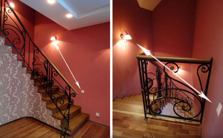
There are often situations when there is a need for lighting a flight of stairs in an entrance with the ability to turn on and off light bulbs at each of its sites. This is the case when without the use of cross switches complete with two loop-through devices, the issue cannot be solved in any way. A similar situation is created if you need to control the lighting in three rooms at once, without constantly returning to the starting point.
The places where lighting switching is conveniently organized using cross-switches also include:
- basements of private houses and country mansions;
- attic rooms of wooden and urban buildings;
- long corridors, often found on office spaces.
This method is also applicable in the case when it is necessary to equip a system for switching on and off the lighting lines in large areas (in exhibition halls, for example). If they are available, it is not necessary to stop it from one end to the other several times a day to control lighting devices from remote points of the site. It is enough to go to the 2-key cross-over switch located in a convenient place and use it to make the necessary commutation.
Principle of operation
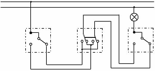
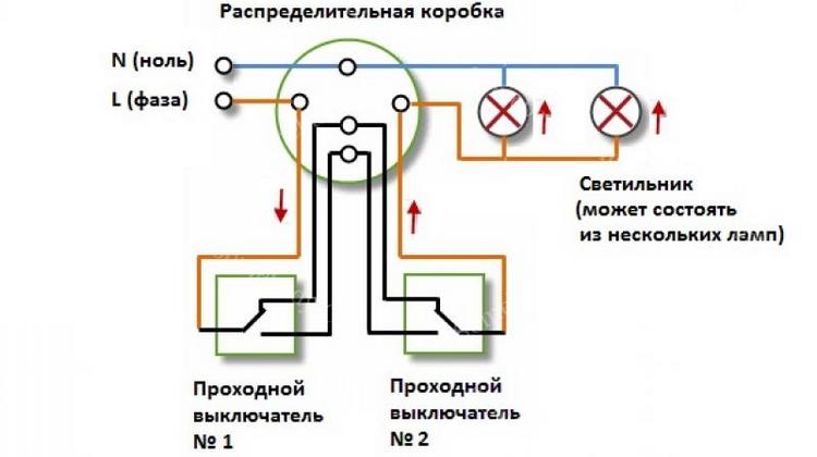
Understanding how the two-key cross-over switch works will help you familiarize yourself with the diagram of the necessary connections. The device is connected to the lighting network as follows:
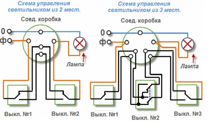
- three switching devices are used in the circuit - two pass-through switches at the edges and one cross located between them;
- an earth conductor or zero from the junction box is laid directly to the light fixture;
- the phase wire is first supplied to the input terminal of one of the through switches;
- then it is pulled from the output terminals to the input contacts of the cross-key switch;
- from it the same wire is switched to the output terminals of the second pass-through switch;
- after that, he enters the lighting device (lamp or chandelier).
Three wires are needed to connect two loop-through switches, and one more will be required for mounting a cross-device.
4-point lighting control
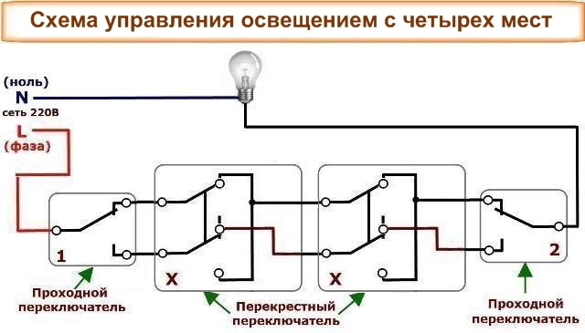 To control the lighting device from 4 places, you will have to use a more complex switching scheme. It consists of two continuous switches and two cross-switches.
Intermediate devices allow you to switch the line from one direction to another or only after that make the switch, characteristic of three points.
In case of concealed wiring, cross and walk-through switches can be mounted in standard embedded boxes.Their installation locations are selected on the basis of expediency, as well as taking into account the ease of use and maintenance. However, in any case, the first should be located in the middle, and the second - along the edges of the general scheme.
Varieties of circuit breakers
In practice, there are several types of cross switches that differ in the type of control and the installation method. In accordance with the first sign, these products have the following designs:
- keyboard instruments;
- rotary devices.
To understand the differences between these options, you need to familiarize yourself with each of them in more detail.
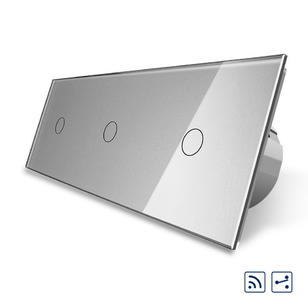
Keyboard devices
Products of this class are in great demand by the consumer, because they are convenient to operate and look quite aesthetically pleasing. With their help, it is possible to break one chain and simultaneously connect another.
Conventional or standard keyboard devices switch only one circuit.
By the number of buttons involved in them, they are single-key (the simplest option), two-key and 3-key. When familiarizing yourself with the wiring diagram, the devices are distinguished by the number of wires supplied to the outlet:
- a single-key walk-through switch has two contact connectors;
- at a simple cross-switch there are 3 of them;
- The two-key crossover device is designed for 4 contacts and wires.
Three-key and two-key cross-switches allow switching several independent circuits with lighting devices. By means of a single-key device, only one circuit can be controlled.
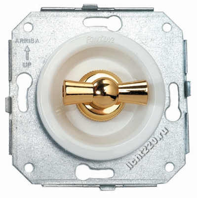
Rotary cross gauges
Switches of this type are not very popular and are most often used at production facilities. They are also in demand in warehouses and, if necessary, control street lighting.
In domestic conditions they are used only in exceptional cases, with high humidity, for example.
To close and open the contacts in these devices uses a special lever mechanism.
Overhead and embedded
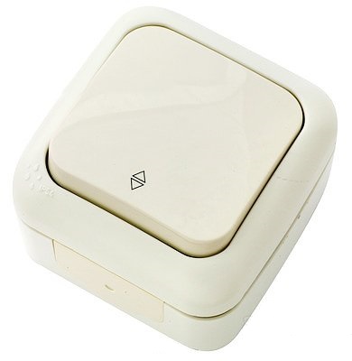
According to the installation method, the switches are divided into built-in and overhead. The first variety of products is mounted even at the stage of building construction or when replacing wiring. In this case, the connecting wires are laid in the thickness of the walls or fixed in cable channels.
Overhead switches are fixed directly on the wall surfaces, so that there is no need for cable channels in this case. The disadvantages of these devices include operating costs due to the possibility of severe pollution. On the other hand, they fit perfectly into modern interiors.
Cross device specifications
In the domestic market there are many models of electrical devices used to control light from 3 places. They are produced both by Russian and foreign manufacturers and differ mainly in their cost. Regardless of the brand and design of the product, its main characteristics are represented by the following parameters:
- The switched voltage is 220 volts.
- The current strength in the circuit is up to 10 Amps.
- Case material - plastic, thermoplastic or polycarbonate.
- Protection class (selected depending on operating conditions).

In products installed in rooms with high humidity, the level of protection is selected with the maximum value.
System Installation Instructions
Control systems with a cross switch are mounted in the following sequence:
- First, a two-wire wire is laid, and then fixed in a convenient way, necessary for connecting through (cross) switches.
- Nearby, small loops are formed, formed on solid wires, after which both devices are installed in selected places.
- Conducted ends of conductors (zero or phase) are connected to the passage devices.
- The power grid is checked for the ability to control lighting from 2 places.
- If the result is positive, the voltage is removed from it by means of a linear machine.
- In de-energized circuits in the area where the crossover device is located, a gap is made in the laid wire, into which the switch itself is then mounted.
- After that, it remains to turn on the power and check the entire system for operability.
During installation, it is necessary to use a cable whose conductors in their cross section correspond to the expected load. When laying control circuits in the entrance or on the street, it is recommended to choose a wire with double insulation.
Features of connecting a two-key switch
To install a double switch, in any case, you need a three-wire cable, even if there is no PE protective earth conductor in the electrical wiring of the apartment. After purchasing the product, you should first disassemble it, for which it is enough to dismantle the keys of the device. You can do this manually by pulling on yourself first one, and then another switching plate. If all else fails - you need to take a screwdriver and pry off its sting key on the side. After that, it is necessary to remove the decorative frame from the switch - it either fastens on latches or is screwed.
Connecting a switching device
As a result of disassembly from the switch, there remains a body with side mounts and an internal toggle mechanism. Its inclusion in the control line is reduced to the supply voltage to the common contact. When each of the keys is closed, the phase will be connected to one of two directions along which the wires are routed to different lighting circuits.
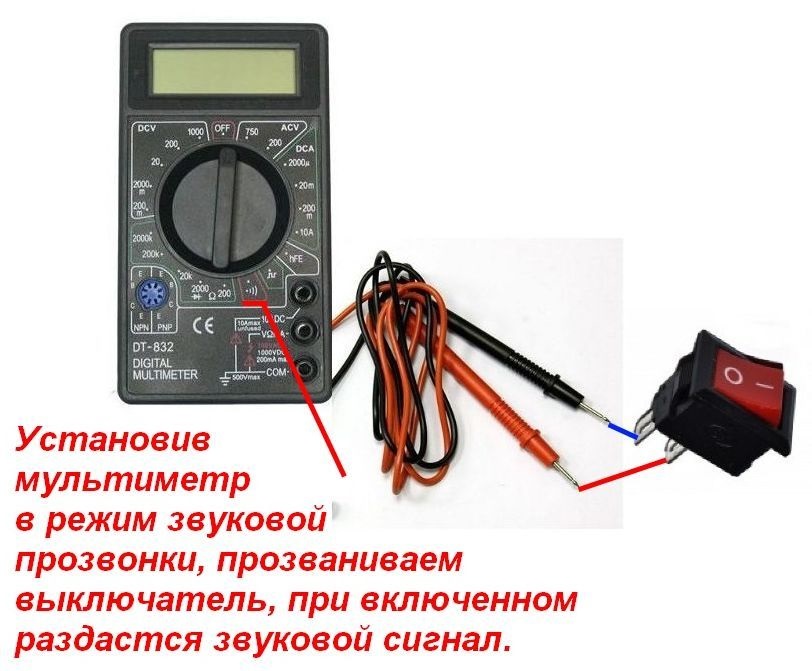
If there is no marking on the device’s case, you will have to use a tester or a multimeter (“Callback” mode). With their help, you can verify the operability of the switching contacts and determine the input and output terminals.
Having dealt with the contacts of the switch, they proceed to arranging the connections, for which a three-core VVGng 3x1.5 cable with wires of various colors will be required. All subsequent operations are carried out in the following order:
- A phase conductor coming from the junction box is connected to the common contact of the switch. It may be insulated in red, brown or gray.
- Proceed to fixing on the contacts of the two conductors extending from the device.
- The housing is installed in the mounting box and fixed in it by means of fixing screws.
- The box itself (glass) is mounted in its place, which is fastened with two long expansion screws.
At the final stage of installation, the decorative frame should be replaced and the previously dismantled keys should be put in place.
Junction box mounting
Inside the electrical distribution box, it is important to distinguish between the following types of wire conductors:
- supply (phase) wire supplied from the linear machine;
- a lead-in conductor with a phase going to the switch;
- one or more wires extending to the illuminator.
In order not to get confused in the circuit breaker circuit, it is necessary to observe a strict sequence of arrangement of connections. According to generally accepted rules, in the first place, a zero core is laid, going directly to the illuminator. The subsequent operations are carried out in the following order:
- You should start by connecting a phase conductor, stretched from a linear machine.
- A conductor stretched from the common phase contact of the two-key cross-over switch is connected to the same terminal.
- Of the remaining four free cores, two are redirected to a chandelier or sconce.
- The rest extend to two output contacts of the switching device.
When considering the connections in the electrical box, the protective earth conductor in yellow-green insulation must be taken into account.
Land is not taken into account only when there is no corresponding wire in the apartment network. If there is enough free space in the box, all connections are formed using clamps such as "nut" or "Wago". In the absence of free spaces, the same type of wire is connected by twisting and then soldering.
Connection on a chandelier or lamp
 In an apartment lamp, chandelier or sconce, special connecting pads are usually used to connect control wires. They start the cores of the cable coming from the junction box, connected according to the color marking.
On any factory fixture, the conductive conductors have a color insulation that meets the generally accepted standard.
Typically, a phase conductor is marked with gray or red insulation, and an earth conductor with blue or blue. The phase is brought to the central contact of an ordinary bulb, and zero is fed to its base.
When arranging cross-switches, compliance with all requirements for their installation is strictly necessary. Only in this case, you can be sure that the lighting control system will function normally.