Contour grounding is installed to protect buildings from fires, and people from electric shocks. When performing work, it is necessary to comply with the requirements of the PUE, correctly calculate, install the circuit and check the level of its resistance.
The device and principle of grounding
In residential premises, a TN system is often installed, the neutral of which is deafly grounded. A ground wire connects all consumers to the protective circuit. The latter has a low resistance, and the current always passes in the circuit where the resistance is less. Compared with the grounding device, the human body is characterized by high resistance, therefore, the circuit allows you to solve the tasks assigned to it.
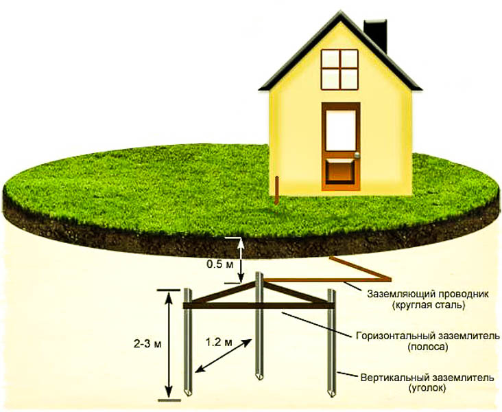
Contour grounding is a system in the form of an equilateral triangle, rectangle or square, assembled from vertical grounding conductors - steel rods or corners, which are connected by welding at the upper points with horizontal steel strips. It is connected to a grounded equipment with a cable. The most common type of construction is triangular.
The outer contour is buried in the ground. The level of resistance to spreading of the currents of the protective device varies depending on the type of soil, its structure.
The best indicators are recorded when installing the ground loop in peaty, loamy and clay soil. In the latter case, provided close to the surface of groundwater. If the soil consists of dense rocky inclusions, indicators deteriorate.
You can assemble the circuit yourself or use a ready-made kit.
Varieties of ground loops
There are several types of structures used for grounding.
Traditional grounding systems
A system of this type consists of a minimum number of elements: two vertical electrodes of metal reinforcement and one horizontal in the form of a strip that connects the two previous ones. The cross-sections and sizes of the elements must comply with the standards. It is recommended to install grounding on the northern shaded side of the site, in a humid place. However, due to the fact that the circuit is often made of steel and it is impossible to cover it with paint, it quickly corrodes. The resistance of such a device is also affected by the temperature and soil moisture level, since the circuit is placed in the upper layers.
Depth Grounding Systems
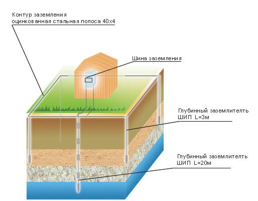
Such a system is manufactured in a modular pin fashion. Compared to the previous version, it differs:
- long service life;
- simple calculations;
- environmental susceptibility;
- lack of need for maintenance;
- ease of installation.
Measurement of the resistance of the installed equipment must be carried out by specialists.
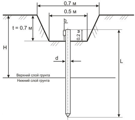
The external ground loop consists of vertical electrodes and horizontal grounding elements. It is made of four strips with a thickness of 40-50 mm and is installed at a distance of at least 1 m from the building. The horizontal strip should be located at a depth of 50 to 70 cm from the surface.
Calculation of the protective circuit
To perform an accurate calculation of the grounding loop, you must consider:
- soil moisture;
- average temperature in winter and summer in the installation area;
- soil resistance and salinity;
- cross-section and length of grounding conductors and electrodes;
- distance from home to the circuit.
The calculation is made according to the formulas, this procedure is difficult for a person who does not have an engineering education. However, even if the correct calculations are made, the actual resistance of the circuit will differ from the calculated one due to the large number of influencing dynamic factors.
In fact, many only take into account the remoteness of the circuit from the foundation, and then adjust the resistance by measuring this indicator of an already mounted structure.
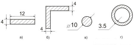
Recommended grounding dimensions:
- stripes - width - 40-50 mm, thickness - 4-5 mm, not less than 2.5 m long;
- corners - shelf thickness - 4-5 mm, shelf width 40-50 mm, at least 2.5 m long;
- rods (necessarily smooth) - cross section 16-20 mm, at least 2.5 m long;
- pipe - wall thickness 3.5 mm, diameter not less than 32 mm, length - not less than 2.5 m.
Exact calculations, taking into account all parameters, must be carried out if it is necessary to ground large commercial and industrial structures.
Objects requiring a contour
It must be grounded:
- premises where machine tools, devices and lighting sources work with metal cases and casings;
- complete transformer substations, as well as buildings in which electrical equipment with steel cases is located;
- secondary winding of the measuring transformer;
- metal pipelines for cables, rooms where metal structures and cables, wires are located at the same time.
It is not necessary to ground devices that are installed on already grounded equipment, circuit breakers in switchboards, electrical measuring devices.
Wiring diagrams
The most common connection schemes include closed triangular and linear. A closed system is more stable in operation, because even if one of the horizontal grounding conductors is damaged, it will continue to fulfill its function. Linear in this sense loses to a closed construction. It stops working if the jumper is damaged.
In addition to linear and triangular designs, oval and rectangular protective devices can be made, but they are less popular.
Ground loop inside the facility
The ground loop is positioned both outdoors and indoors. When creating it indoors, you must follow the rules:
- Do not use central heating, sewage and similar pipelines, supporting cables, metal sleeves, armored wires as zero protective conductors.
- Grounding and neutral conductors are laid in an open way, since they must be accessible for inspection, and painted in yellow-green strips.
- Passages through walls and ceilings are formed using non-metallic fireproof pipes.
- Steel tires are painted, welded joints are treated with oil paint.
- In damp rooms, conductors are welded to supports.
These are the basic rules, but there are others that are relevant when laying the internal circuit in rooms with an aggressive environment, in the shops of industrial enterprises.
Ground loop installation

According to the classical installation order of the ground loop, preparatory work is first performed, then the device is installed directly and resistance is measured.
Preparation for installation
For installation, it is necessary to prepare the tools:
- a shovel;
- a grinder or hacksaw for metal;
- welding inverter;
- hammer drill;
- wrenches at 8, 10;
- current, voltage, resistance meters.

Of the materials required:
- Corners made of corrosion-resistant steel, 40 × 40 × 4/50 × 50 × 5 cm and a length of at least 2.5 m. Or steel round bars with a diameter of 20 mm.
- Three metal strips 250 cm long, 40 to 60 mm wide and 5 mm thick. The greater the distance between the electrodes, the better the spreading of currents, since electromagnetic fields interact less with each other. Ideally, the distance between the electrodes should correspond to their length or increase by a multiple of this parameter.
- Stainless steel strip for connecting the circuit to the foundation 40 × 4 or 50 × 5 mm or power cable.
- Bolts M8, M10.
- Copper conductor.
Place for installation of the circuit should be located close to the foundation and distribution panel.
Mounting the safety device
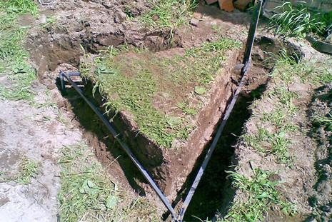
The first step is to make trenches with a depth of about 80 cm under the ground loop and the strip connecting the system to the foundation. The configuration of the trenches must match the shape of the ground loop. In this case, grounding is performed in the form of a triangle with sides measuring 2.5 m each.
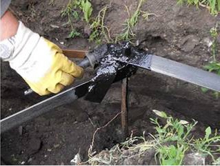
Metal corners should be sharpened so that they enter the ground more easily. They are driven into the soil, and not dug holes. The electrodes should enter the ground tightly. Jumpers are welded to the electrodes. Welds are treated with bituminous mastic to protect against corrosion. Cable along the trench lead into the house, to the electrical panel. To do this, with the help of bolts and nuts, fix the cable packed in the end contact to the vertical ground electrode. To do this, use tires made of copper (10 mm2), aluminum (16 mm2) or metal (75 mm2). First they fill the circuit with sand, then with earth.
Measurement of the resistance of the protective device
To monitor the operability of the device, it is recommended to measure its resistance to current spreading according to all the rules. Work is best done in winter or summer, when the soil resistance is maximum. For the norm of the resistance of the protective circuit, indicators of 15, 30, 60 Ohms or 2, 4 and 8 Ohms are taken when measured with natural earthing switches and repeated earthing switches of the outgoing lines for the network 660-380, 380-220 or 220-127 V, respectively.
Loop resistance test
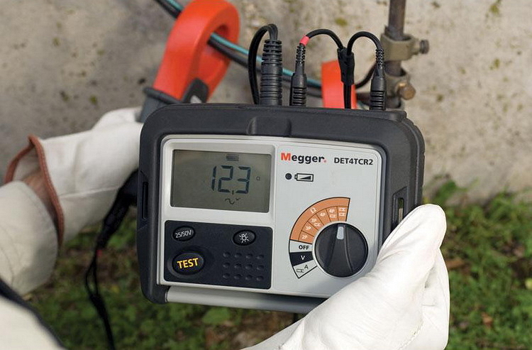
To measure the grounding correctly, special measuring devices should be used - “MS-08” or “MS-416” and test electrodes. The technique is as follows:
- A potential electrode is placed between the circuit and the house at a distance of at least 20 m. Another in a straight line with the first and protective device, at a distance of not more than 40 m.
- By connecting voltage, measure the resistance.
- Grounding measurement is carried out several times, gradually bringing the remote electrode closer, but not closer than 5 m.
The determination of the resistance value is performed according to the worst result obtained.
Most common mistakes
When installing a grounding device, the following errors are most often made:
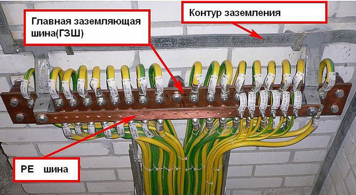
- The circuit is connected to the wrong point in the electrical installation, for example, directly to the equipment. It must be connected to the main ground bus.
- Instead of a circuit, a water supply, heating pipe or the like is used. They can be grounding structures with some reservations and not always.
- Lack of connection of the neutral conductor in the grounding device, as well as the installation of separate circuit breakers in the neutral conductor.
- The use of reinforcement, buried metal objects, working scratch, fences as earthing switches.
- Use of ground loops made of small section elements.
- Weld less than 10 cm.
- Welds are not treated with bitumen mastics from corrosion.
- A strip of contour that emerges from the ground is not painted. It should be painted black or yellow-green.
- Insufficient length of horizontal and vertical earthing.
- Insufficient deepening of horizontal elements.
- They establish a ground loop, but do not ground the main communications, consisting of metal elements: water supply, heating, gas supply, sewage.
It must be possible to disconnect the grounding device from the electrical installation for making measurements, that is, the strip that exits the grounding device must be disconnected. This possibility is provided by a bolted connection of elements.
If the installation is made in accordance with all the rules, it was possible to properly measure the resistance and the indicators correspond to the norm, the building is reliably protected from a short circuit and its consequences.