Loading circuit breakers is one of the methods used to verify the correct functioning of this type of device and their compliance with established state standards. You can load the circuit breaker with a unit assembled according to a special scheme.
Machine loading basics
The main functions of automatic switches are the activation and opening of electrical circuits. The latter process is initiated when the voltage drops seriously below normal, the circuit is overloaded or a short circuit incident occurs. When the craftsmen do the loading of the automatic machines, they aim to check the correct functioning of the releases by passing an electric current through them coming from a specially designed installation.
Among the situations in which it is recommended to perform this procedure include:
- overhaul of a switch or other electrical equipment;
- purchase of a new device;
- completion of repair of an electrical installation.
Also, scheduled preventive loading is carried out with a certain frequency established at the enterprise. The mechanism of the procedure is based on the effect of the electromagnet on the release, as a result of which the latter is activated and the device stops working. A properly organized procedure will reveal if the device is able to protect the network from various unpleasant incidents. It should protect against fire and excessive loads (frequent occurrences due to damage to the insulating material of wires and pressure drops) and from the user receiving an electric shock in a short-circuited circuit. If the device has passed the tests, it is recognized as serviceable and suitable for routine use.
Main characteristics of circuit breakers
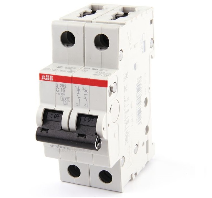
Circuit breakers belong to the category of protective devices. They protect the electrical circuit from the effects of a short circuit: when an incident occurs, the device must immediately turn off so that there is no arcing or burning. For electrical equipment, different types of machines are used, suitable for technical specifications. To work with voltages less than 1000 V, molded-case circuit breakers (withstand currents up to 3.2 kA), air power switches (critical indicator 6.3 kA), and devices with a modular structure are used.
All switches are equipped with two protective releases located inside the body of the appliance. Electromagnetic protects against a short-circuited situation, while thermal protects equipment and electrical circuits from overload.
The main characteristics of the devices include:
- tripping current - the value at which the switch is activated in case of overload or short circuit;
- the time interval after which the device is triggered;
- the rated current at which the device can function normally.
During the loading procedure, these indicators are measured. The procedure cannot be called simple, only highly qualified personnel of the electrical laboratory after special training are allowed to implement it.
AB loading device
The method of loading circuit breakers involves the artificial creation of a closed circuit with the option of gradual adjustment of the electric current index. This principle applies to any commercial machine loader. There are devices designed for different values of the rated current.
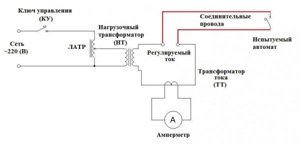
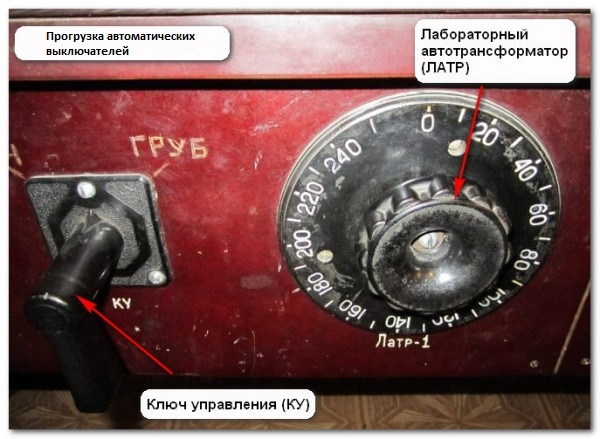
You can assemble the installation yourself. One example is a design using three types of transformer devices: one of them is responsible for the load, the other works with electric current, and the third is a laboratory automatic device. The circuit also includes a shunt ammeter, a control key, a stopwatch and cables. The function of the latter is to connect the circuit breaker under test with the terminals of the controlled current. Such a design can create an electric current of about 50 A on the secondary coil of the load transformer. You can use it to test switches designed for high currents, but then you need a power source and a load device with high power.
Automatic loading technique
Automatic loading is done according to a single algorithm. First you need to study the technical documentation of the device and determine the characteristics that need to be checked. Then the operation of the releases is tested: first they always work with the electromagnetic unit, then with the thermal one. Then the results are recorded in the prepared protocol on the work performed.
Example
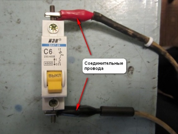
You can demonstrate the procedure using the example of a switch from a domestic manufacturer VA47-29. The protection class of this device is C, which corresponds to the need for a five-fold excess of the rated current (which is equal to 6 A) in order for the electromagnetic protection to work. It is this degree of protection that is most common with circuit breakers used in ordinary household networks.
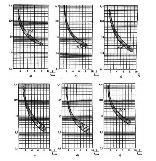
Before connecting the device to the test installation, you need to study the technical documentation attached to it. It contains a graphical representation of the time-current response characteristics. The abscissa axis represents an excess of the rated current by the loading current. The ordinate axis is the time period after which thermal protection is activated.
Having studied the graph, it can be understood that the zone in which the electromagnetic release is activated covers the range of exceeding the electric current rating (6 A) by 5-10 times. Thus, to turn on this kind of protection, a current of 30-60 A is required. This mechanism works almost instantly: during normal operation, the time should not exceed 0.02 s. For practical experience, you can take an eight-fold excess (48 A), in this case, turning off the machine from the network should occur no later than after 0.01 s.
As for the thermal protective mechanism, on the graph, the switching interval is limited to a pair of curves reflecting the normal and heated state of the switch. Three times the rated current (18 A) will be used for verification. The use of an electric current of such a multiplicity for testing is a traditional indicator, unless there is an indication of another recommended multiplicity in the instrument passport. The value of the time after which the machine will turn off should be in the range from 3 to 80 s (this can be found on the schedule).
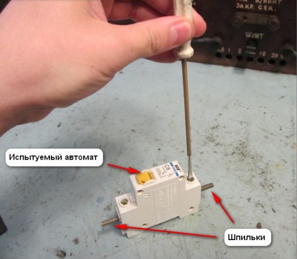
When any of the releases does not cut down the device in the required time period, the switch is recognized as defective and is not allowed for subsequent operation. To make it easier to load the device, you can put on it long leads made of studs. Cables are connected to them.
Protocol and frequency of loading
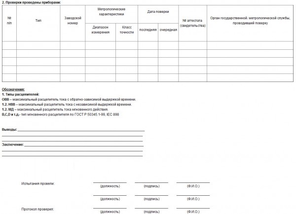
Before starting the test tests, it is advisable to make a heading of the protocol in which the results will be entered. The following parameters are indicated in the document:
- time delay setpoints;
- varieties of tested releases;
- response time of each of the investigated protections;
- values of short circuit current and overload;
- exposure time of each current;
- current values at which the device operates and remains static;
- features of the reaction of defenses during test events.
-

- Protocol page 1

-

- Protocol page 2
If the data obtained complies with the established standards, the device is recommended for commissioning. If malfunctions were detected during loading operations, a special document is prepared that indicates the nature of the violations and recommendations for their elimination in accordance with the EMP.
Periodicity
The rules for the installation of electrical installations, as well as the Rules for the technical operation of electrical installations of consumers in no way regulate the frequency of scheduled tests. However, regular loading at regular intervals is advisable, as machines have the ability to develop their resource over time. In the passport or other documentation attached to the device, the manufacturer indicates the recommended intervals between tests. In production, such periods are established by the technical manager. Most often, scheduled procedures are recommended every three years. This applies to devices installed in industrial power grids and used for domestic purposes. Additional checks are carried out when installing new equipment or overhauling old ones.
Regular loading of these machines will allow you to determine the malfunction of the device in time. This will prevent disturbances in the functioning of electrical networks.