The voltage control relays (LV) installed immediately after the meter and the RCD allow instantly breaking the power supply circuit in the event of an emergency. These devices respond to strong fluctuations in the amplitude of the supply voltage and are able to protect consumers connected not only to single-phase, but also to three-phase networks. When installing them, the voltage relay connection scheme, which does not allow the slightest deviation from the requirements of current standards, acquires special importance.
Types of ILV by voltage type
Known examples of voltage monitoring relays primarily differ in the type of power supply, according to which they are divided into single-phase and three-phase models. The first are installed in urban apartments and are designed to protect loads in linear circuits of 220 volts without re-grounding. Their three-phase analogues are used in power lines of industrial facilities or in private homes, the owners of which received permission to connect the appropriate equipment to 380 volts. The presence of grounding in this case is considered mandatory.
Three-phase ILV has one significant drawback, consisting in the fact that when overloaded on one of the phases, it disconnects all three lines at once. Some experts consider this property to be an advantage, on the contrary, since in this case it is possible to save all the equipment operated in this line. It acquires special importance in production, where a separate load is connected to each of the phase branches. In everyday life, when operating a pump motor, for example, it rather interferes with normal operation. Small voltage fluctuations in one of the phases in this case do not have much significance.
Varieties of ILV by other parameters
In addition to differences in the type of power supply, these devices differ in a number of characteristics that determine the method of their installation, and in functionality.
Type of execution and dimensions
In accordance with this feature, all ILV models manufactured by the industry are divided into three types:
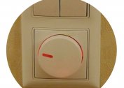
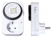
- adapters of the "plug-socket" type;
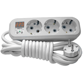
- extension cords with several sockets (from one to six);
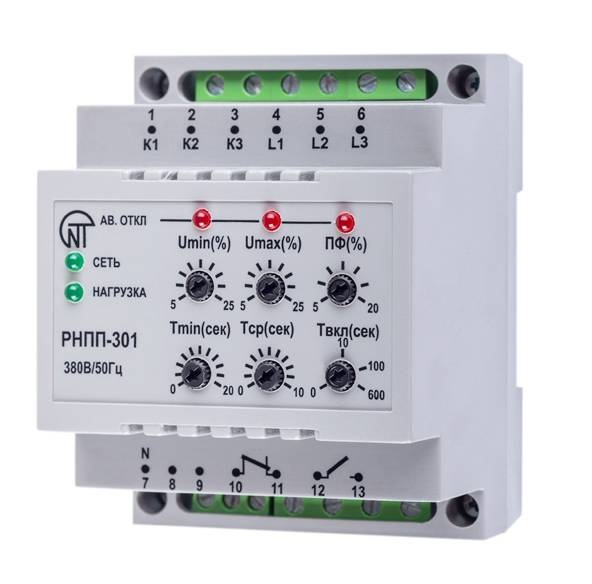
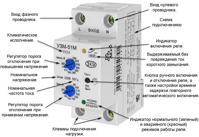
- compact switches mounted on a DIN rail in a panel.
-
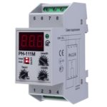
- Single-phase voltage relay RN-111M 1F NOVATEK

-

- Voltage relay with plug and socket
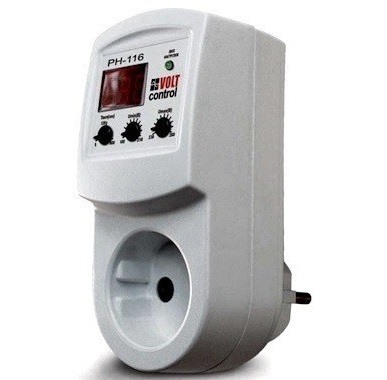
-
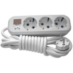
- Extension cord with voltage relay
The first two product variants are used to protect individual electrical appliances or several consumers in groups. They plug into a regular power outlet. Devices of the third type are installed in an electrical panel, in which the remaining protection devices are mounted.
Cases of adapters and extension cords are made quite convenient to use. Manufacturers are trying to reduce their size as much as possible so that they do not spoil their interiors.
The devices mounted on a DIN rail are more compact in size, since additional devices are not required for their inclusion. Wires are brought to them in the same way as when installing conventional automatic machines or RCDs.
Base and additional features
According to the internal logic of operation and electronic stuffing, all known ILV samples are divided into microprocessor products and devices made on the basis of digital comparators.The first ones are somewhat more expensive, but they provide more accurate and smooth adjustment of the lower and upper thresholds. Most of these protective devices are microprocessor-based and stand out among other products with the following features:
- the presence of two thresholds (Umax and Umin);
- the use of built-in LEDs mounted in the instrument panel - they control the presence of voltage at the input and output;
- the use of a liquid crystal display on which the values of the permissible deviation limits and the effective voltage are displayed.
All these features significantly increase the functionality of devices and simplify the work with them when installed in an apartment or a private house.
ILV Connection Diagrams
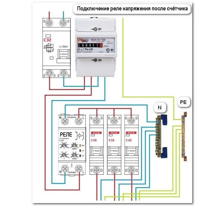
Before connecting a voltage relay, you will need to carefully study the typical circuitry of the electrical cabinet. When installing it, the voltage relay must be installed after the meter in the gap of the phase wire, sometimes an RCD is connected between them, connected as necessary. With this arrangement, the surge protector will cut off precisely the "phase".
For normal operation, phase and ground are fed simultaneously to its input terminals.
There are two schemes for connecting single-phase and three-phase relays to the consumption line:
- with direct load through ILV;
- with connecting the consumer through the contactor, which is part of the magnetic starter.
In each of these cases, it is possible to connect several devices in parallel, each of which can connect its own consumer group.
When installing electrical panels in an apartment or a private house, the connection scheme with direct load through the ILV is most often used.
Setting operation modes
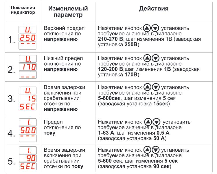
The threshold values of the ILV are set using potentiometers placed on the front panel and having a graduated scale.
In some relay samples, buttons for displaying parameters on an electronic board are used for this.
When setting the required threshold values, their exact values are controlled by the display built into the front panel of the device. After the initial setting for these indicators, the need for their reinstallation, as a rule, does not arise.
Which is better: relay or stabilizer
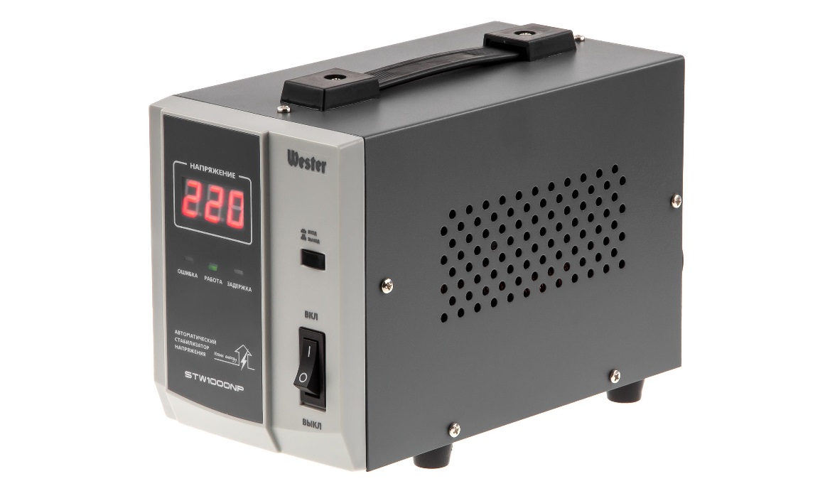
Instead of monitoring relays, some users use a typical voltage regulator in their home. In some cases, such a decision is considered justified. However, there are several nuances taken into account when choosing a reliable method of protecting electrical appliances. First of all, you need to keep in mind that they perform similar functions and can disconnect the load in an emergency. But the difference in their work is still there and is manifested in the following:
- stabilizers are characterized by increased noise level and are much more expensive;
- they are more inertial, especially when tracking sudden voltage drops;
- they do not provide for the ability to adjust the installation parameters;
- these devices take up much more space.
When the input signal decreases, the stabilizer begins to consume more current, which is explained by the need to maintain the output voltage at a constant level.
The main disadvantage of the stabilizer compared to the ILV is the inability to respond to sudden voltage drops in the network when the neutral wire is broken.
Only a fraction of a second is enough for a voltage surge of 350–380 Volts to burn out all household appliances connected to outlets. Most of the samples of electronic stabilizers produced by the domestic industry are not able to respond to short-term pulsations. In the characteristics of stationary devices, a reaction time of not more than 1-2 seconds is provided.Therefore, the right approach to choosing a protection device is a guarantee of the safety of the equipment connected to it.
Features of the voltage relay in three-phase networks
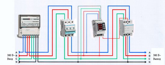
In three-phase circuits, a particular danger is the inclusion of a relay with reduced voltage, the connection circuit of which does not provide for a single-phase operation of the device. In most cases, in industrial networks, a separate load is connected to each phase. This leads to the fact that triggering the overload of one section of the ILV leads to its complete shutdown.
An exception is the situation when three-phase equipment (machines with induction motors, pumps and the like) is mainly used at the facility. In this case, each of the phases is loaded more evenly and voltage overload practically does not occur.
Regardless of the type of ILV, for their normal operation it will be necessary to choose the right scheme and installation location.