Modern LED light sources are well adapted for long-term operation in difficult conditions. However, current limiting resistance is used for current protection. Accurate calculation of the resistor for the LED will help to select the functional components of the circuit without errors.
The use of a current-limiting resistor for the LED
For decorative decoration, ensuring good visibility in a darkened corridor and solving other practical problems, LEDs are used. They are much more economical compared to classic incandescent bulbs. High strength prevents environmental contamination with harmful chemical compounds, which is not excluded after damage to the bulb of a gas-discharge light source.
Given the one-sided conductivity of the semiconductor junction, the need to connect the LED to the battery, another DC power source, is understandable. The voltage of a standard household network is rectified, reduced to a nominal level. The resistor limits the current strength.
Features of work and calculations
Despite the significant advantages, attentive users recommend paying attention to the significant disadvantages of LED devices:
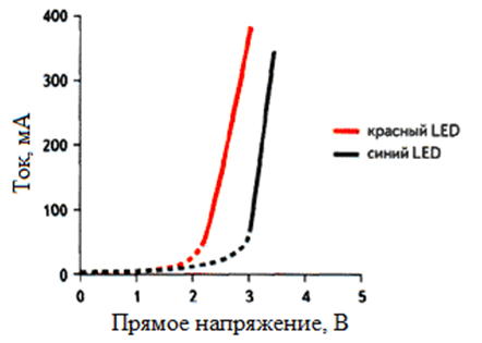
- semiconductor technology determines non-linear current-voltage characteristics (CVC);
- voltage increase above a certain threshold is accompanied by degradation of the pn junction;
- at a certain level (with direct or reverse switching on), a sharp increase in amperage damages the product.
Of particular importance is its own small resistance in the operating mode. A relatively small change in the main parameters of the power source can damage the semiconductor junction. For this reason, a current limiting resistor is added to the circuit.
An additional passive element increases energy consumption. For this reason, it is recommended to use such solutions in combination with light-emitting diodes of small power, or to create devices with small duty cycles.
Mathematical calculation
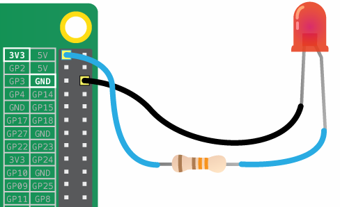
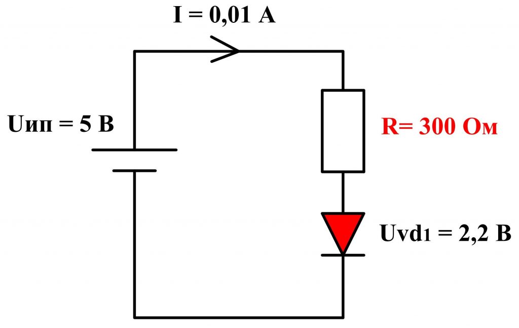
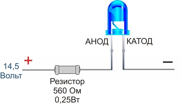
In the simplest circuit, a current-limiting resistor (R) and an LED are connected in series to a constant current source (I) with a specific voltage (U and) at the output terminals. The electrical resistance can be calculated using the well-known Ohm's law formula (I = U / R).
The second postulate of Kirchhoff is also useful. In this example, it defines the following equality: Uand = Ur + Ucwhere Ur (Uc) - voltage across the resistor (LED), respectively. By simple conversion of these expressions, you can get the basic dependencies:
- Ui = I * R + I * Rc;
- R = (U and - Uc) / I.
Here Rc denotes the differential resistance of a semiconductor device, which varies nonlinearly depending on voltage and current. On the reverse part of the current-voltage characteristic, a locking region can be distinguished. Significant increase Rc on this site prevents the movement of electrons (Iobr = 0). However, with a subsequent increase in voltage at a certain level (Urebr-m), a breakdown of the p-n junction occurs.
Since the driver provides direct current power, you need to carefully study the appropriate “direct” connection. Features of the CVC:
- on the first stretch to Un the resistance gradually decreases and the current increases accordingly;
- from Un before Um - working area (radiation in the light range);
- further - a sharp decrease in resistance provokes an exponential increase in current strength with subsequent failure of the product.
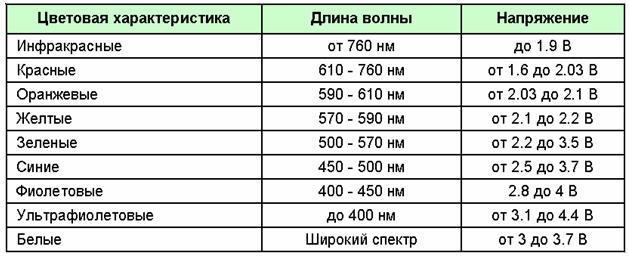
LEDs are calculated based on the value of the operating voltage Uc. Manufacturers indicate this parameter in the accompanying documentation. To calculate the electrical resistance of a suitable current-limiting resistor, use the formula: R = (U and - Uc) / I.
Graphic calculation
If you take the I – V characteristic, you can apply the graphic technique. Original graphic and digital information is taken from the passport, or on the official website of the manufacturer. Algorithm of actions (example):
- according to the source data, the nominal current of the LED (In) is 25 mA;
- a dotted line is drawn from the corresponding point (1) on the vertical ordinate axis to the intersection with the I – V curve (2);
- note the voltage of the power source (U and = 5.5 V) on the abscissa axis (3);
- draw a line through points (2) and (3);
- the intersection with the ordinate axis will show the value of the maximum permissible current (Im = 60 mA).
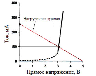
Further, according to the classical formula, it is not difficult to calculate which resistor is needed for the LED in this case: R = U and / Im = 5.5 / 0.06 ≈ 91.7. In the series, you need to choose the closest rating with a small margin of 100 ohms. This solution will slightly reduce the efficiency. But in sparing mode, the functional components will heat less. Correspondingly, the load on the semiconductor junction will decrease. Expect an increase in the life of the light source.
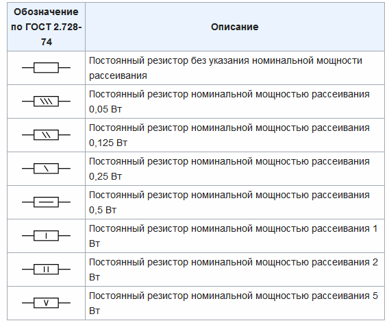
For the correct choice of resistor, you need to know the power (P). Standard values (W): 0.125; 0.25; 0.5; 1; 2; 5. Calculations can be done by any known parameters using the formulas: P = Im2 * R = Ur2 / R. If we take the initial data of the considered example: P = 0.06 * 0.06 * 100 = 0, 36 W. Given the type range, you must choose a resistor with a resistance of 100 Ohms with a dissipation power of 0.5 watts.
Tolerances on the accuracy of the electrical resistance of the resistors are from 0.001 to 30% of the nominal. In the marking according to international standards, the corresponding classes are indicated in Latin letters (D - 0.5%; G - 2%; J - 5%).
Connecting an LED through a resistor
Based on the data presented, several important intermediate conclusions can be made:
- resistive protective circuits are used at low power;
- they do not perform stabilization functions;
- the passive element is not able to suppress surges.
Acceptable performance indicators can be obtained by creating:
- sensors;
- indicators;
- signaling devices.
For a small local aquarium illumination, such a solution is suitable. However, prolonged consumption of large amounts of energy is unlikely to be acceptable. The lack of stabilization is manifested by a noticeable change in brightness with increasing / decreasing voltage.
Experts recommend that with a total consumption of more than 1.5-2 W, use power supplies with reliable current stabilization. These devices (dimmers) are used to connect groups of lighting devices and semiconductor devices of high power.
Calculation of the resistor for the LED
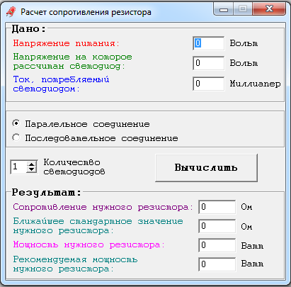
You can make the necessary calculations online using a specialized calculator. The full use of such programs is offered for free.
However, access to the Internet is not always available. After studying a fairly simple technique, anyone can quickly select a resistor for the LED without searching for the appropriate software.
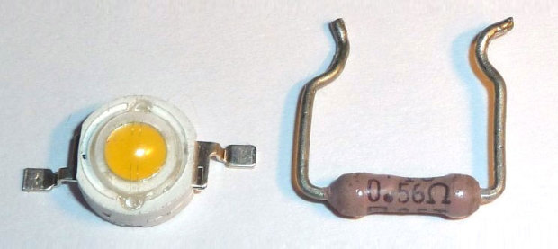
To demonstrate the algorithm, you need to consider connecting a protective resistor to the power circuit (5 V) of a particular LED (Epistar 1W HP).
Technical specifications:
- power dissipation, W - 1;
- current, mA - 350;
- forward voltage (typical / max.), V - 2.35 / 2.6.
To limit the LED current, taking into account the manufacturer's recommendations, a resistor with an electrical resistance of R = (5-2.35) /0.35 = 7.57 Ohms is suitable. According to the E24 standard, the nearest values are 7.5 and 8.2 Ohms. If you use the standard rules, you will have to choose a larger value that differs from the estimated value by almost 8.5%. An additional error will be created by 5% tolerance of serial inexpensive products. With such a deviation, it is difficult to obtain circuit characteristics acceptable in terms of protective functions and power consumption.
The first way to solve the problem is to select several resistors with lower ratings. Then apply a serial, parallel or combined version of the connection to obtain the necessary equivalent resistance of the circuit. The second method is adding a tuning resistor.
Power dissipation calculation
In any of the options, when choosing the electrical resistance of the circuit, a slightly lower current should be set to extend the life of the LED. To prevent damage by heat, the product is used in the recommended temperature range. For Epistar 1W HP, -40 ° C to + 80 ° C. If necessary, use mounting on a specialized star radiator. This supplement increases the effective heat dissipation area.
For accurate selection, the dissipated power of the resistor is estimated: P = I2 * R = (0.35) 2 * 7.57 = 0.1225 * 7.57 ≈0.93 W. The reserve for this parameter is not less than 20-25%. A rating of 1 W is not enough, so choose the next rating in the standard row - 2 W.
The efficiency of the assembled circuit is checked by the ratio Uc / Uи = 2.35 / 5 = 0.47 (47%). The final result shows that more than half of the electricity in this case is wasted. In fact, the indicator is even worse, since not all power consumption is spent by the LED on radiation in the visible part of the spectrum. A significant part is electromagnetic waves of the IR range.
Parallel connection
At any point in the series circuit, the current strength is the same. This simplifies the calculation, prevents emergency situations. When one element fails, all LEDs turn off. Therefore, damage by overvoltage is excluded. The noted reasons explain the popularity of the use of this method when creating tape lamps, other designs.
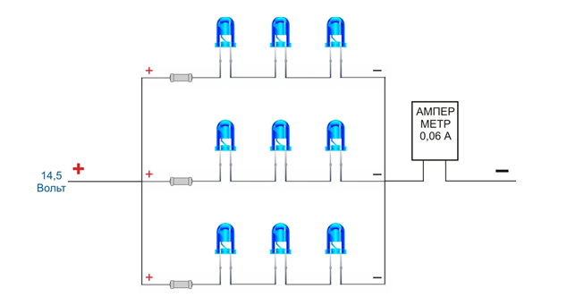
Certain advantages are provided by the use of parallel connection. In this embodiment, the product retains partial operability when one circuit is damaged. This solution provides the same voltage at the points of connection to the power source of each branch.
Parallel connection is suitable for the organization of independent control circuits. This technology is based on the principles of the work of New Year's garlands. Separate branches are connected to the power source according to the algorithm specified by the program.
You cannot use one resistor for several parallel diodes. A careful choice of resistance is explained by the need for precise current control. In some situations, errors of 0.1-0.5 A cause breakdowns, a radical reduction in resource.
The actual technical characteristics of LEDs differ significantly even in the same consignment. For this reason, each circuit is protected by a separate resistor.
Features of cheap ICE
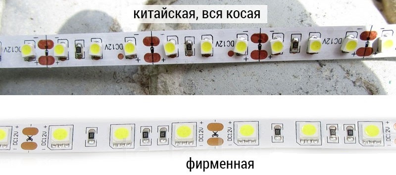
Low cost alone is not proof of poor quality. Expanding the scale of production and improving technological processes reduces costs.However, products of manufacturers that actually do not correspond to the declared characteristics are presented in the corresponding market segment.
To identify possible problems, pay attention to the following parameters:
- in cheap models, the main parts of the structure are made of aluminum;
- copper analogs are heavier, more efficiently remove heat, are resistant to mechanical stress;
- in a quality product, the crystal size complies with the standard (0.762 x 0.762 mm or another);
- the disadvantages are indirectly indicated by the distortion of the proportions of the working area (a rectangle instead of a square);
- To increase reliability, responsible manufacturers increase the number of conductors, use threads from precious metals.
High-quality LEDs create a luminous flux of 150-220 lumens per 1 W of consumption. Fakes - no more than 50-70 lm. When in doubt, the protection components should be selected with particular care.